Micro channel type heat exchanger

a heat exchanger and micro-channel technology, applied in the direction of tubular elements, lighting and heating apparatus, stationary conduit assemblies, etc., can solve the problems of pressure loss generation, micro-channel heat exchangers are more difficult to fabricate in two columns, and micro-channel heat exchangers generally require a higher initial investment cost, so as to minimize thermal loss

Active Publication Date: 2022-03-22
LG ELECTRONICS INC
View PDF16 Cites 0 Cited by
  • Summary
  • Abstract
  • Description
  • Claims
  • Application Information

AI Technical Summary

Benefits of technology

[0010]An object of the invention is directed to a micro channel type heat exchanger having a structure that is capable of minimizing a thermal loss through a fixed plate for separating headers.
[0011]Another object of the invention is directed to a micro channel type heat exchanger having a structure capable of reducing a pressure loss of a refrigerant when it is used as an evaporator.

Problems solved by technology

In contrast, the micro channel type heat exchanger generally requires a higher initial investment cost because it is fabricated using a brazing process.
The pin tube type heat exchanger can be easily fabricated with them stacked in two columns, whereas the micro channel type heat exchanger is more difficult to fabricate in two columns because it is put into a furnace and fabricated.
However, if the conventional micro channel type heat exchanger is used as an evaporator, there is a problem in that a pressure loss is generated because a refrigerant is evaporated in the process of the refrigerant flowing from the first column 1 to the second column 2.

Method used


Image

  • Micro channel type heat exchanger
  • Micro channel type heat exchanger
  • Micro channel type heat exchanger

Examples


first embodiment

[0046]A micro channel type heat exchanger according a first embodiment is described with reference to FIGS. 2 through 7.

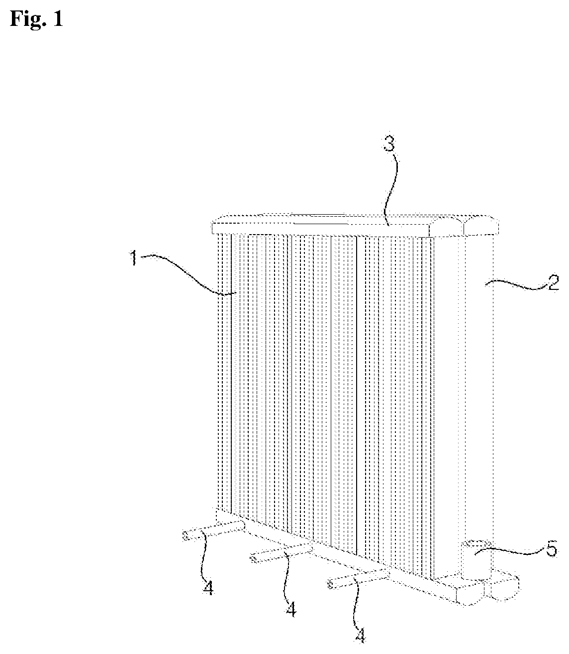
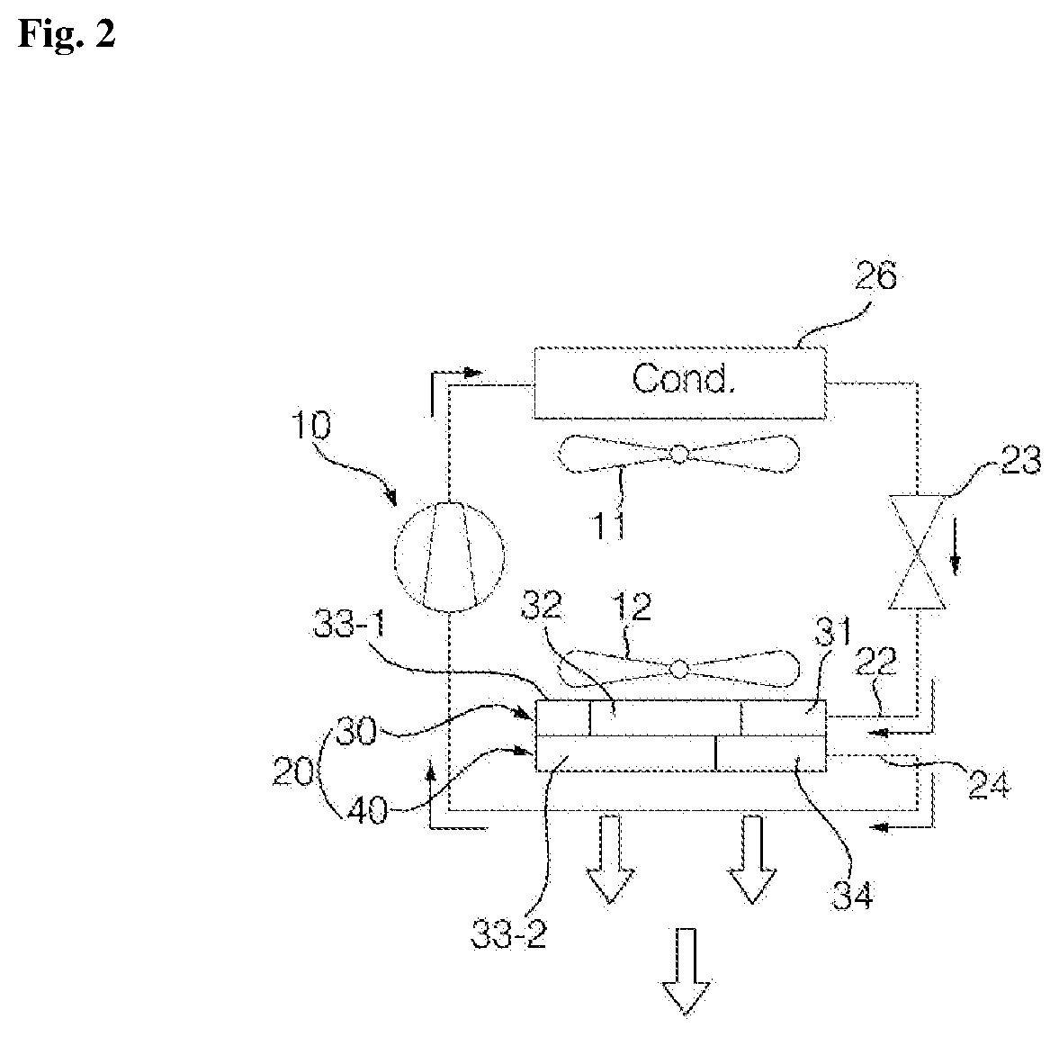
[0047]As illustrated, an air-conditioner may include a compressor 10 configured to compress a refrigerant, a condensation heat exchanger 26 configured to be supplied with the refrigerant from the compressor 10 and to condense the supplied refrigerant, an expansion unit 23 configured to expand the fluid refrigerant condensed by the condensation heat exchanger, and an evaporation heat exchanger 20 configured to evaporate the refrigerant expanded by the expansion unit 23.

[0048]It is understood that the expansion unit 23 may comprise, for example, an electronic expansion valve (eev) or a Bi-flow valve or a capillary tube.

[0049]The air-conditioner may further include a condensation ventilation fan 11 configured to flow air into the condensation heat exchanger 26 and an evaporation ventilation fan 12 configured to flow air into the evaporation heat exchanger 20.

[0050]An ...

second embodiment

[0131]the present invention is described below with reference to the embodiment illustrated in FIG. 9.

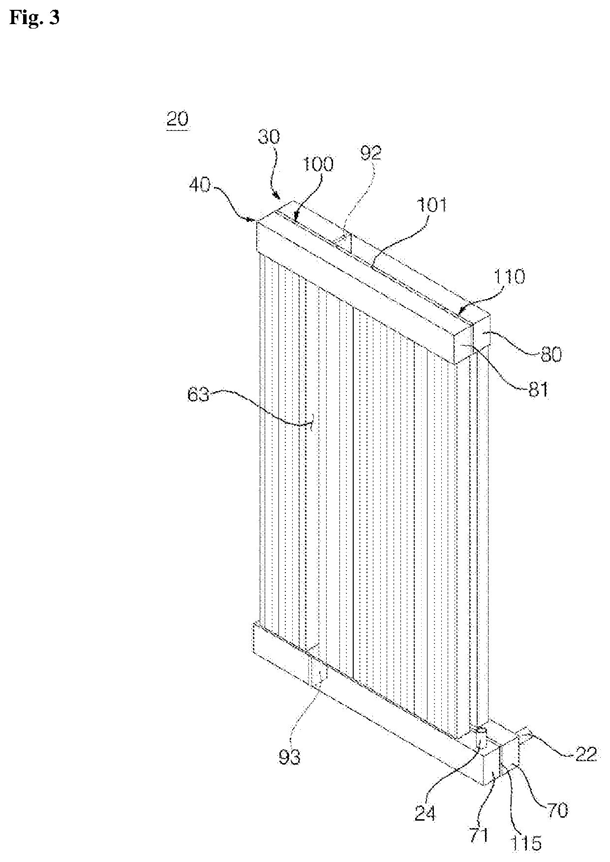
[0132]Unlike in the first embodiment, a heat blocking member 120 according to the second embodiment is not located between headers, but connects the headers. As described above, the heat blocking members according to the first embodiment are inserted between the headers and fixed thereto. In contrast, the heat blocking member 120 according to the second embodiment connects the outsides of the headers.

[0133]More particularly, for example, the heat blocking member 120 connects the first and the second lower headers 70 and 71 or connects the first and the second upper headers 80 and 81. The heat blocking member 120 may be curved along the outside surfaces of the first and the second lower headers 70 and 71. It is understood, however, that the heat blocking member 120 may be formed in a plate-like shape. The heat blocking member 120 can be fixed to the first and the second lower headers...

third embodiment

[0136]the present invention is described below with reference to the embodiment illustrated in FIG. 10.

[0137]In the third embodiment, a heat blocking member 130 is similar to that of the second embodiment, but further includes an insertion part 135 inserted between headers. As shown, the insertion part 135 may be inserted between the first and the second lower headers 70 and 71 and fixed thereto.

[0138]A heat blocking space 101 may be secured by the insertion part 135. The insertion part 135 may support the first heat exchange module 30 and the second heat exchange module 40. Although an external impact is applied, the heat blocking space 101 is maintained by the insertion part 135.

[0139]The heat blocking member 130 may be disposed at the first and the second upper headers 80 and 81. The heat blocking member 130 may be disposed at the first and the second lower headers 70 and 71.

[0140]The remaining elements of the third embodiment are the same as those of the second embodiment, and t...


PUM


Abstract

A micro channel type heat exchanger in which a first heat exchange module and a second heat exchange module are stacked, the micro channel type heat exchanger including a plurality of flat tubes disposed within the first heat exchange module and the second heat exchange module, and a heat blocking member configured to form a heat blocking space by separating the first heat exchange module and the second heat exchange module, wherein the heat blocking member forms a heat blocking space between the first heat exchange module and the second heat exchange module that minimizes heat conductivity and improves thermal exchange performance of the heat exchanger.

Description

CROSS-REFERENCE TO RELATED APPLICATION[0001]The application claims priority under 35 U.S.C. § 119 to Korean Patent Application No. 10-2015-0129285, filed Sep. 11, 2015, whose entire disclosure is hereby incorporated by reference.BACKGROUND OF THE INVENTION[0002]1. Field of the Invention[0003]A micro channel type heat exchanger.[0004]2. Discussion of the Related Art[0005]In general, a heat exchanger may be used as a condenser or evaporator in a freezing cycle device including a compressor, a condenser, an expansion unit, and an evaporator. The heat exchanger may be classified as either a pin tube type heat exchanger or a micro channel type heat exchanger depending on its structure.[0006]Generally, the pin tube type heat exchanger is made of copper and the micro channel type heat exchanger is made of aluminum. The micro channel type heat exchanger is generally more efficient than the pin tube type heat exchanger because a fine flow channel is formed therein. The pin tube type heat exc...

Claims


Application Information

Patent Timeline
Patent Type & Authority Patents(United States)
IPC IPC(8): F28D1/053F28F9/02F28D1/04F28F1/12F28D21/00
CPCF28D1/05391F28D1/0417F28D1/0435F28F1/124F28F9/0202F28F9/0204F28F9/0212F28D2021/0071F28F2260/02F28F2270/00
Inventor KIM, BEOMCHANRYU, BYOUNGJINYANG, TAEMANCHUNG, CHOONMYUN
Owner LG ELECTRONICS INC
Why Eureka
Try Eureka