Supercharge Your Innovation With Domain-Expert AI Agents!

Box clamping mechanism

A clamping mechanism and box technology, which is applied in the stacking, transportation and packaging of objects, can solve the problems of production line restrictions and production line efficiency, and achieve the effect of high work efficiency and flexible clamping

Inactive Publication Date: 2010-03-17
DONGGUAN ANWELL DIGITAL MASCH CO LTD
View PDF0 Cites 0 Cited by
  • Summary
  • Abstract
  • Description
  • Claims
  • Application Information

AI Technical Summary

Problems solved by technology

In the case of relatively compact space, such as inside the cavity, due to the size limit of the cavity door, these box clamping mechanisms often cannot simply and effectively realize the clamping action of the box, so that the link of the production line is limited, so that the whole The efficiency of production lines is affected

Method used


Image

  • Box clamping mechanism
  • Box clamping mechanism
  • Box clamping mechanism

Examples


Embodiment Construction

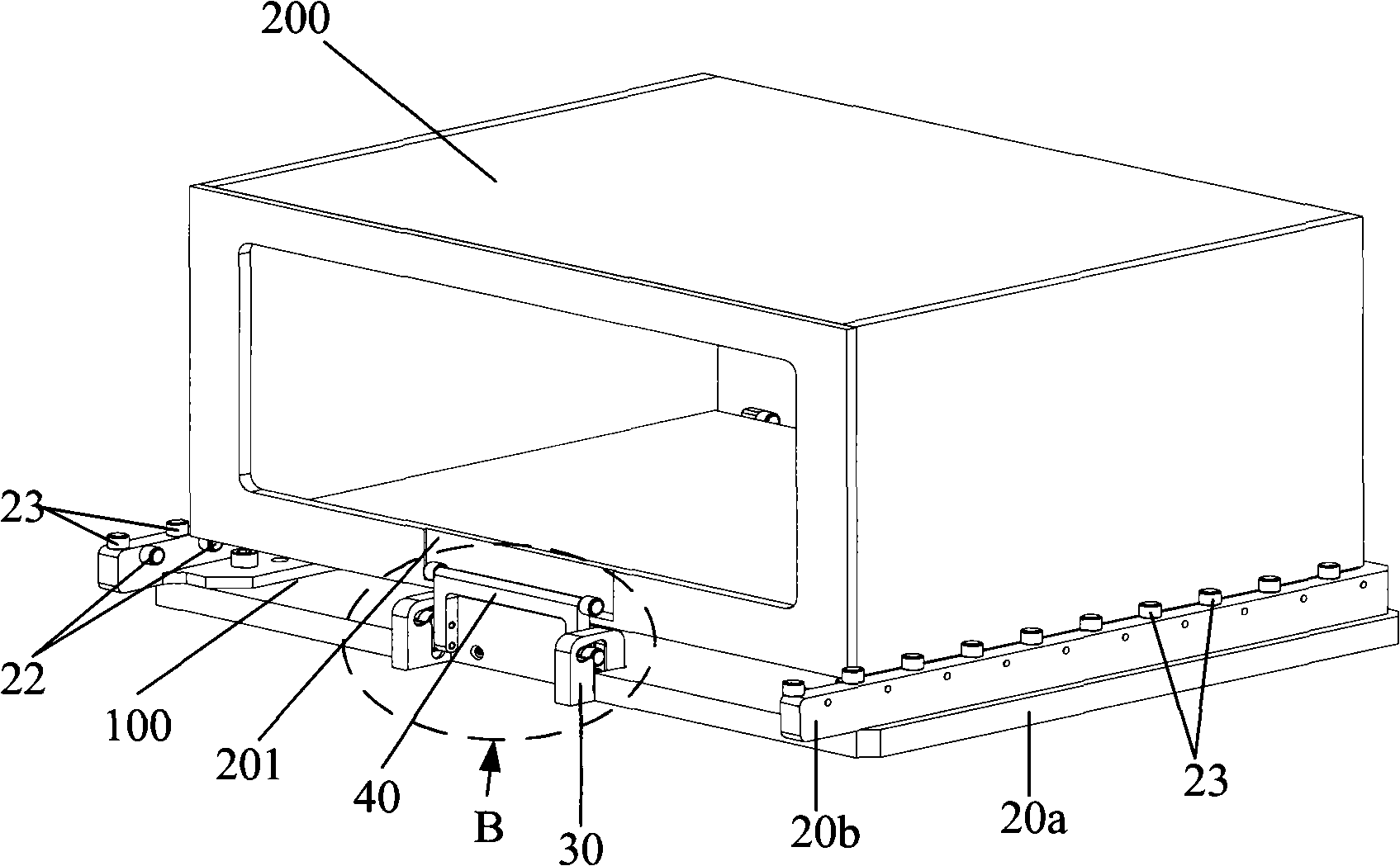
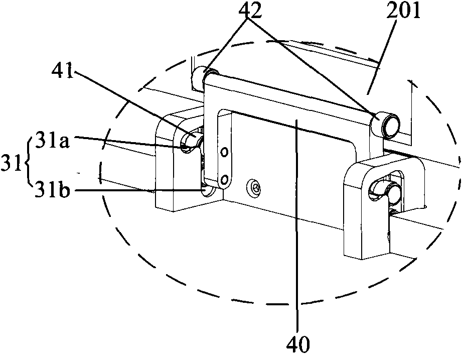
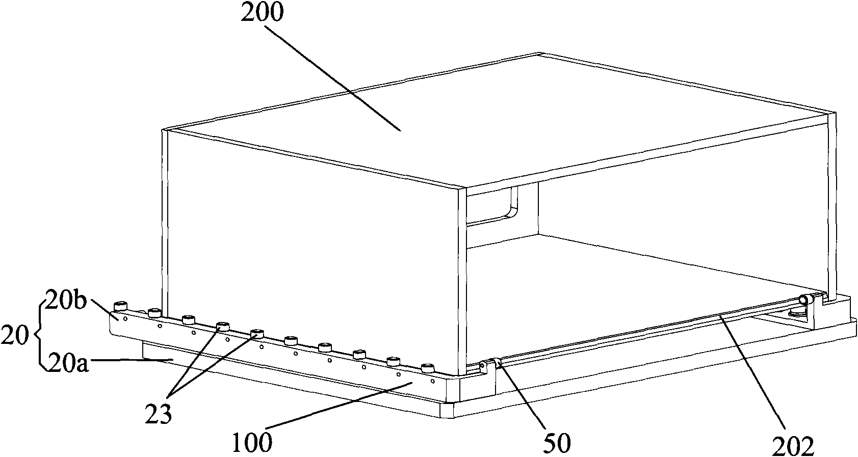
[0025] figure 1 It is an application embodiment of a box clamping mechanism of the present invention, such as Figure 1-4 As shown, in this embodiment, the box 200 is carried on the box clamping mechanism 100 and is in a clamped state. The box clamping mechanism 100 includes a bottom plate 10, two fixing seats 20, a guide block 30, a handle 40 and a limit roller 50, and the two fixing seats 20 are protrudingly fixedly connected to both sides of the bottom plate 10, so The limit roller 50 is connected to the rear end of the fixed seat 20, the guide block 30 is fixedly connected to the front end of the bottom plate 10, and the two sides of the guide block 30 are parallel to each other and have a curved rolling chute 31, sliding rollers 41 are pivotally connected to both sides of the lower end of the handle 40, and the sliding rollers 41 are slidably locked in the rolling chute 31. In this embodiment, the number of sliding rollers 41 There are two, and the matching of multiple ...


PUM


Abstract

The invention discloses a box clamping mechanism comprising a bottom plate, two fixed seats, a guide block and a gripe for locking a workpiece, wherein the two fixed seats are respectively connected at both sides of the bottom plate fixedly, the back ends of the fixed seats are provided with spacing rollers, the guide block is fixedly connected at the front end of the bottom plate, both sides of the guide block are provided with rolling sliding chutes, both sides of the lower end of the gripe are provided with sliding rollers, and the sliding rollers can be clamped and arranged in the rollingsliding chutes in a free glide way. Because both sides of the guide block of the invention are mutually parallel and are provided with the rolling sliding chutes which are in a bending shape, the sliding rollers at the lower end of the gripe are clamped and arranged in the rolling sliding chutes in a sliding way, the gripe is pulled after a box is placed at a placement position formed by the fixedseats, the spacing rollers and the guide block on the bottom plate, and a stop roller of the gripe is placed in a sliding chute which is arranged along the longitudinal direction on the side wall ofthe front end of the box, therefore, the locking of the box is realized, the mounting and the clamping are flexible, and the work efficiency is high.

Description

technical field [0001] The invention relates to a clamping mechanism, in particular to a box clamping mechanism for conveying and clamping boxes on a palletizer in an automatic production line. Background technique [0002] In modern automated production lines, it is often necessary to move the workpiece from one station to the next, and sometimes it needs to move back and forth according to the requirements of the process. Such as the transmission of boxes on the palletizer, the box needs to be positioned during the transmission process, and the effectiveness of clamping has become an important factor for positioning accuracy. Prior art box clamping mechanisms generally clamp the box from the bottom of the box. In the case of relatively compact space, such as inside the cavity, due to the size limit of the cavity door, these box clamping mechanisms often cannot simply and effectively realize the clamping action of the box, so that the link of the production line is limited...

Claims


Application Information

Patent Timeline
IPC IPC(8): B65G57/00
Inventor 杨明生刘惠森范继良郭业祥王曼媛王勇
Owner DONGGUAN ANWELL DIGITAL MASCH CO LTD
Features
  • R&D
  • Intellectual Property
  • Life Sciences
  • Materials
  • Tech Scout
  • Unparalleled Data Quality
  • Higher Quality Content
  • 60% Fewer Hallucinations
Learn More