

Decoding device and decoding method
A decoding device and decoding technology, applied in the field of signal decoding, can solve problems such as decoding errors and wrong judgments of the decoder 6, and achieve the effect of improving the accuracy rate and avoiding decoding errors
- Summary
- Abstract
- Description
- Claims
- Application Information
AI Technical Summary
Problems solved by technology
Method used
Image

Examples
Embodiment Construction
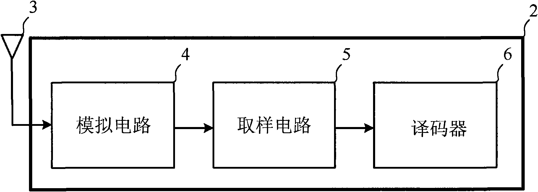
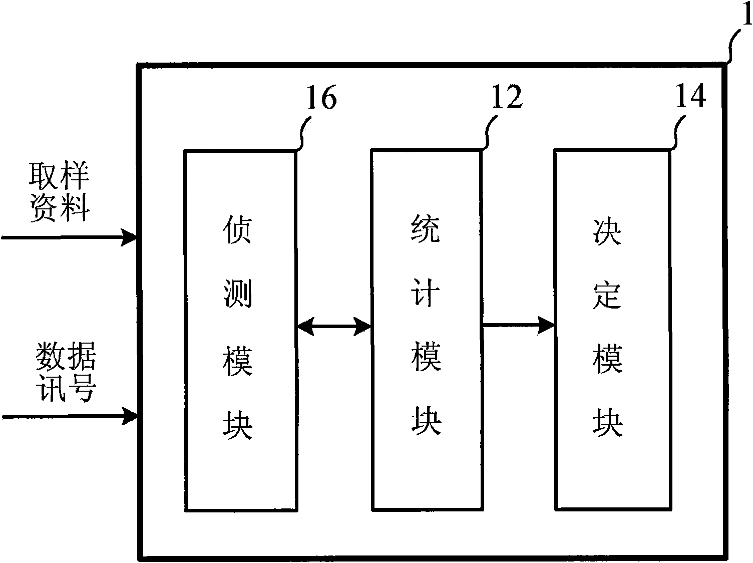
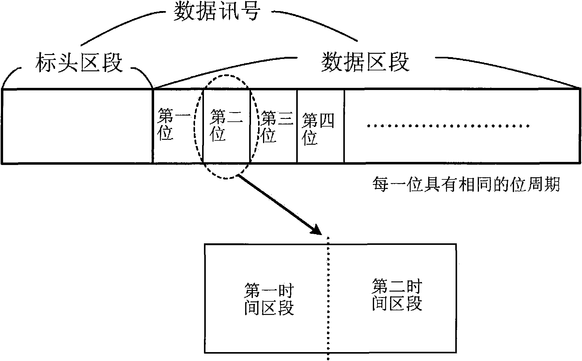
[0033] The first embodiment of the present invention is a decoding device. In this embodiment, the decoding device can be applied in an RFID system, and is used for decoding a data signal including a plurality of bits. After the data signal is sampled, a plurality of sampled data can be generated. Such as image 3 As shown, the data signal includes a header segment and a data segment, the data segment follows the header segment and includes the plurality of bits. Each of the plurality of bits has the same bit period.
[0034] In this embodiment, the data signal can be encoded by Manchester encoding method, differential Manchester encoding method or other similar encoding methods. The so-called "Manchester encoding" is a common encoding used in many local area networks. Its main characteristic is that no matter the digital logic value of a bit of the data signal is 0 or 1, ideally there will be a transition between a high logic level and a low logic level near the center of...
PUM
 Abstract
Description
Claims
Application Information