Electric measuring tape

A tape measure and electric technology, applied in the direction of the bendable ruler, etc., can solve the problem that the tape is not fast enough to enter and exit, the winding is not very compact, and the tape is damaged, so as to eliminate the phenomenon of "swelling tape", enter and exit quickly and smoothly, and change small effect

Inactive Publication Date: 2011-07-13
NINGBO JUFENG TOOLS IND
View PDF3 Cites 0 Cited by
  • Summary
  • Abstract
  • Description
  • Claims
  • Application Information

AI Technical Summary

Problems solved by technology

[0004] Although the appearance of the electric tape measure is convenient to use, there are still the following problems that have not been solved: the winding of the tape core is not very compact during the process of pulling out and winding the tape under the action of the motor, commonly known as the phenomenon of "swelling tape". Make the ruler tape in and out not smooth enough, which will affect the subsequent use, and may seriously damage the tape

Method used


Image

  • Electric measuring tape
  • Electric measuring tape
  • Electric measuring tape

Examples


Embodiment 1

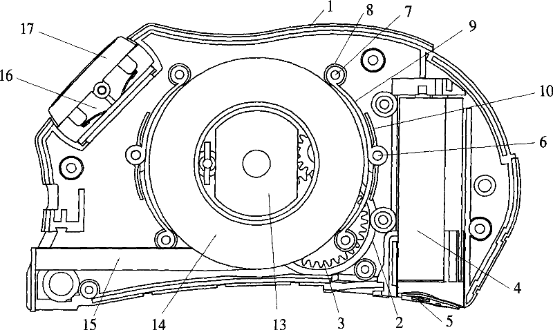
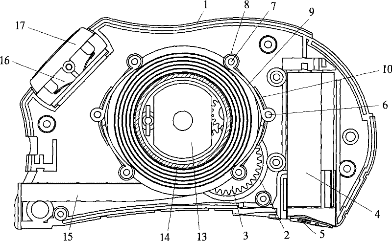
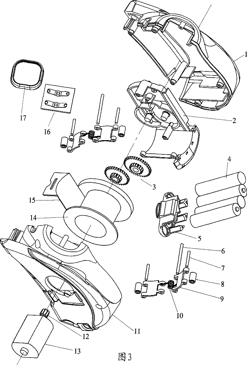
[0033] Example 1: Reference figure 1 , figure 2 , image 3 and Figure 4 As shown, the electric tape measure in this embodiment includes a scale housing, a scale core disc 14, a motor 13, a battery 4, a switch 16, a transmission mechanism and an automatic tightening mechanism.

[0034] The scale shell is composed of the regular scale shell 1 and the reverse scale shell 11, and has accommodating space. The scale core disc 14 is rotatably arranged in the middle cavity of the scale shell and is wound with a scale tape 15.

[0035] The motor 13 is located in the scale housing, and is linked with the scale core disc 14 through a transmission mechanism to realize the extension and retraction of the scale tape. Angle, the mouth that forms scale shell to accommodate electric motor 13 cavity like this is big and the bottom is little, and motor 13 can guarantee the cooperation precision and the accuracy of motor 13 and scale shell by packing into outside scale shell.

[0036] Switc...

Embodiment 2

[0042] Example 2: Reference Figure 5 As shown, the driving member of the automatic tightening mechanism in this embodiment adopts the reed 9a, and the reed 9a acts as a rotating arm.

[0043] The reed 9a is generally in the shape of a herringbone, and the intersecting transition part of the reed 9a is rotatably arranged on the inner wall of the scale housing through a reed shaft 6a, and the reed shaft 6a is wrapped with an open bushing to play a protective and position-limiting effect. There are two rollers 8, which are respectively rotatably arranged on the bifurcated end of the reed 9a through the roller shaft 7, and the roller 13 abuts against the tape 15 on the ruler core disc 14 under the self elastic force of the reed 9a. Other structures and working principles are the same as in Embodiment 1.

Embodiment 3

[0044] Example 3: Reference Figure 6 As shown, the driving part of the automatic clamping mechanism in this embodiment adopts a compression spring 10a, one end of the compression spring 10a is connected to the outer side of the rotating arm 9, and the other end is connected to the protrusion 1a on the inner wall of the scale housing. Other structures and working principles are the same as in Embodiment 1.


PUM


Abstract

The invention relates to an electric measuring tape which comprises a measuring tape shell, a measuring tape core disc and a motor, wherein the measuring tape shell is provided with a containing space; the measuring tape core disc is rotatablely arranged inside the measuring tape shell and wound with a measuring tape belt; and the motor is also positioned inside the measuring tape shell and is linked with the measuring tape core disc by a transmission mechanism so as to stretch and contract the measuring tape from the measuring tape shell. The electric measuring tape is characterized in that the peripheral surface of the measuring tape core disc is provided with an automatic clamping mechanism which forces the measuring tape belt to be compactly wound on the measuring tape core disc all the time. Compared with the prior art, the electric measuring tape has the advantages that as the automatic clamping mechanism which forces the measuring tape belt to be compactly wound on the measuring tape core disc all the time is added, the phenomenon of expanded belt can be avoided, the probability of damaging the measuring tape belt can be reduced, and the measuring tape is ensured to be operated normally.

Description

technical field [0001] The invention relates to an electric tape measure, in particular to an electric tape measure in which the tape wound on the core is always in a tight state. Background technique [0002] Existing tape measures that are generally in use all need to be pulled out of the tape by hand directly from the case, and rely on the return action of the coil spring or turn the handle to wind up the tape, which is not very convenient to use. [0003] For this reason, there are many electric tape measures, and this type of electric tape measure can realize that the pulling out and winding of the tape are all completed by the switch by controlling the steering of the motor. An electric tape measure generally includes a ruler case, a ruler core disc and a motor, etc. The ruler case has accommodating space. The core disk is linked to realize the extension and retraction of the aforementioned scale housing of the tape measure. Refer to the Chinese utility model patent ...

Claims


Application Information

Patent Timeline
Patent Type & Authority Patents(China)
IPC IPC(8): G01B3/10
Inventor 黄忠华
Owner NINGBO JUFENG TOOLS IND
Why Eureka
Try Eureka