
Elastic fibre laying die, laying device comprising such a die, and use of said device

A laying and fiber technology, applied in the field of laying devices, can solve the problems of complicated preform methods

Active Publication Date: 2010-03-24
EADS DEUT GMBH
View PDF11 Cites 9 Cited by
  • Summary
  • Abstract
  • Description
  • Claims
  • Application Information

AI Technical Summary

Problems solved by technology

[0005] However, the known methods for producing preforms are complex in view of their implementation and processing technology

Method used


Image

  • Elastic fibre laying die, laying device comprising such a die, and use of said device
  • Elastic fibre laying die, laying device comprising such a die, and use of said device
  • Elastic fibre laying die, laying device comprising such a die, and use of said device

Examples


Embodiment Construction

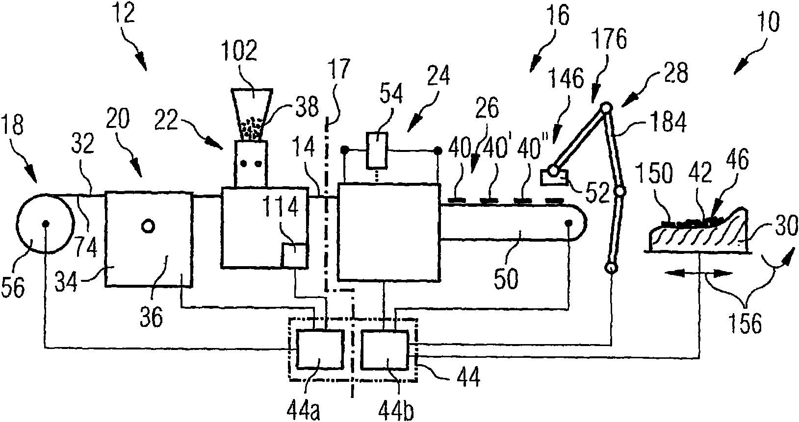
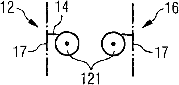
[0045] figure 1 A general view of the preform manufacturing plant, generally indicated by reference numeral 10, is shown. The preform production device allows complex textile semi-finished products to be produced from fiber filaments aligned in the load flow, so that fiber composite structures can be produced in a simple manner even in the case of semi-finished products with complex structures. This textile semi-finished product is called a preform. These preforms consist of individual staple fiber segments held in place by a binder material in accordance with figure 1 Manufactured in advanced equipment, these fiber segments can be pre-cut from specially pretreated fiber tows or fiber tapes. Thus, the preform manufacturing plant may comprise a preparation module 12 for possible preparation of the fiber tape 14 and a cutting and laying module 16 for cutting and laying the fiber tape segments. A possible demarcation 15 between modules 12 and 16 is indicated by a dotted line. ...


PUM


Abstract

A laying device (28) that is configured to lay fiber pieces (40, 40', 40'') has a flexible surface (164) that applies and presses the fiber pieces against a preform surface.

Description

technical field [0001] The invention relates to a depositing device for depositing fiber segments. The invention also relates to a laying mold used in the laying device. The depositing device according to the invention is particularly suitable for use in a method for producing preforms of fiber composite structures arranged in load flow. Background technique [0002] In the construction of all types of vehicles, especially in the construction of aircraft and spacecraft, but also in other branches of industry such as mechanical engineering, there is an increasing demand for strong, lightweight and cost-effective materials. In particular, fiber composites have outstanding potential for lightweight construction. The principle lies in the fact that particularly strong and stiff fibers are embedded in the matrix in such a way that they are aligned with the load flow, so that by using existing technologies a component with remarkable mechanical properties can be produced that we...

Claims


Application Information

Patent Timeline
Patent Type & Authority Applications(China)
IPC IPC(8): B29B11/16B29C70/38B29C70/54
CPCB29K2083/00B29B11/16B29K2707/04B29C70/386B29C70/541B29K2105/12B29C70/545B29C35/02B29C70/543B29C2793/0072B29C31/085Y10T156/1702Y10T156/1705
Inventor O·迈尔S·朔佩
Owner EADS DEUT GMBH
Learn More