
Motor structure assembly

A technology of structural components and motors, applied in the direction of electric components, electrical components, electromechanical devices, etc., can solve problems such as structural space and structural size restrictions

Inactive Publication Date: 2017-07-14
BAUMULLER NURNBERG GMBH
View PDF9 Cites 0 Cited by
  • Summary
  • Abstract
  • Description
  • Claims
  • Application Information

AI Technical Summary

Problems solved by technology

The available installation space is therefore disadvantageously reduced or limited due to the large overall size of the electric motor

Method used


Image

  • Motor structure assembly
  • Motor structure assembly
  • Motor structure assembly

Examples


Embodiment Construction

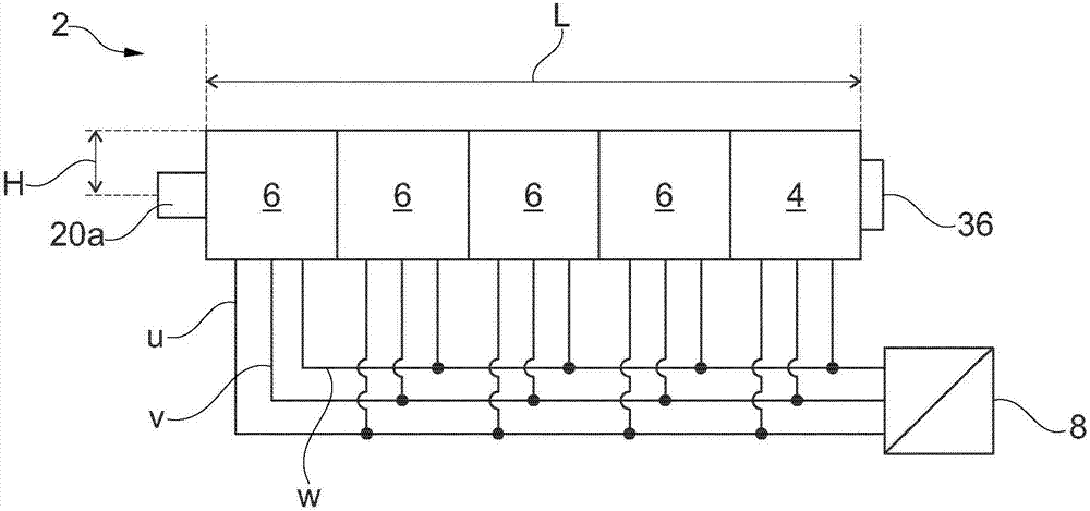
[0030] exist figure 1The motor subassembly 2 of a not-shown adjustment drive of the rack handling device is shown schematically in simplified form. The elongated motor assembly 2 comprises a servomotor 4 arranged on the end side and four electric motors 6 arranged one behind the other. The motors 4 and 6 of the motor assembly 2 are electrically and mechanically coupled to each other. The motors 4 and 6 , which are preferably embodied as brushless electric motors, are energized during operation with three motor phases u, v, w and are connected in parallel to a common converter 8 for this purpose.

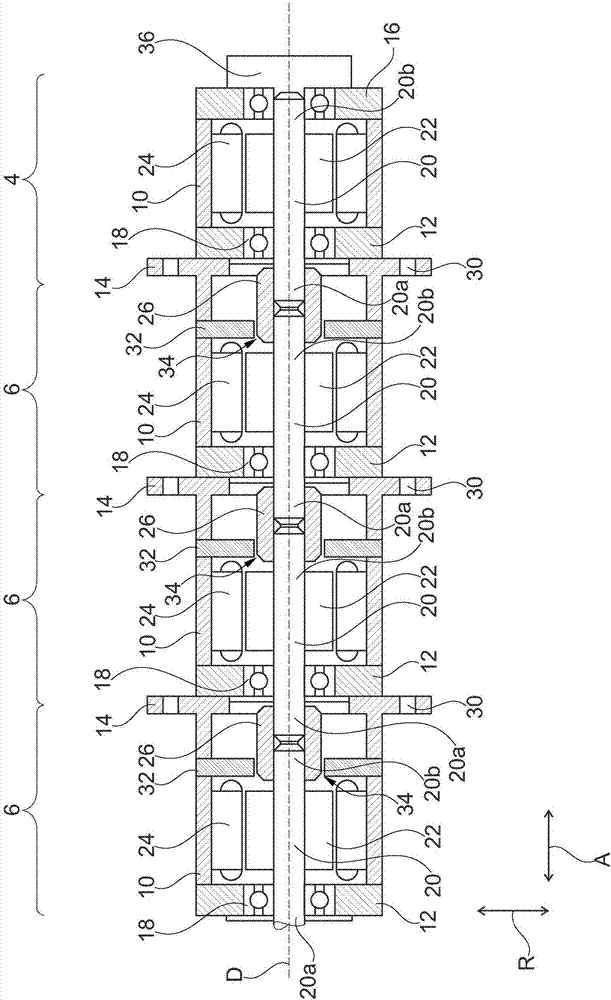
[0031] figure 2 The motor subassembly 2 is shown in section with an axial direction A and a radial direction R. The section extends along a common axis of rotation D of the motors 4 and 6 , which is oriented parallel to the axial direction A. The radial direction R is oriented here in particular along the shaft height H of the motor subassembly 2 , wherein the axial direction A ...


PUM


Abstract

The invention relates to a motor structure assembly (2), which is provided with multiple electric motors (6) arranged sequentially along the same rotating axis (D). Each electric motor is provided with a stator (24), a rotor (22) and a motor shaft (20) supporting the rotor, wherein the motor shafts (20) of all the electric motors (6) arranged sequentially are connected at end sides. The adjacent motor shafts (20) of the electric motors (6) are connected by means of connecting members (26) fixed with the shafts. The connecting members and shaft end portions (20a, 20b) of the corresponding motor shafts (20) are connected in a shape locking way or in a force locking way. Each electric motor (6) has a motor housing (10), a bearing cover (12) at an A side and a bearing-free flange cover (14) at a B side.

Description

technical field [0001] The invention relates to a motor assembly with a plurality of electric motors, each with a stator and a rotor and a motor shaft carrying the rotors. The invention also relates to an adjustment drive equipped with such a motor assembly. Background technique [0002] An electric motor is preferably understood here to be a brushless electric motor (DC motor). Brushless electric motors generally have a shaft-fixed rotor, which is set in rotational motion by means of a housing-fixed stator. For this purpose, the stator includes a plurality of coils, which are energized by means of electronics. The individual coils are electrically connected to one another either in a so-called delta connection or in a star connection as a rotating field winding. During operation, a rotating magnetic field is generated by the rotating field winding, which drives the rotor. [0003] Such electric motors are usually closed at the housing end sides, in particular at the B s...

Claims


Application Information

Patent Timeline
IPC IPC(8): H02K16/00H02K7/00
Inventor 弗里茨·雷纳·戈茨
Owner BAUMULLER NURNBERG GMBH
Learn More