Transmission emergency unlocking means

A technology for emergency unlocking and derailleurs, applied in transmission control, components with teeth, belts/chains/gears, etc., can solve problems such as large structure space, and achieve the effect of small structure space and space saving

Active Publication Date: 2014-07-30
AUDI AG
View PDF8 Cites 15 Cited by
  • Summary
  • Abstract
  • Description
  • Claims
  • Application Information

AI Technical Summary

Problems solved by technology

[0007] Conventional transmission emergency release devices require a large installation space and can only be installed without problems in larger motor vehicles

Method used


Image

  • Transmission emergency unlocking means
  • Transmission emergency unlocking means
  • Transmission emergency unlocking means

Examples


Embodiment Construction

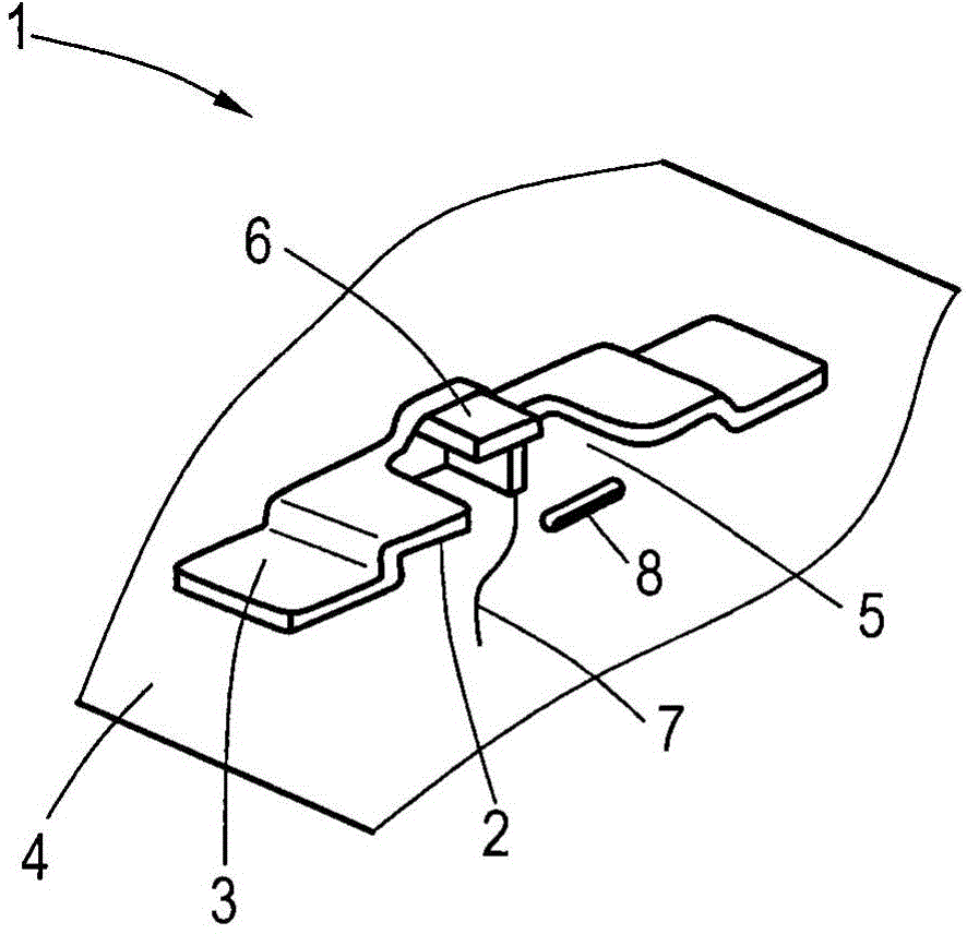
[0042] figure 1 A perspective view of a receptacle 1 fastened to a motor vehicle as part of an actuating element of a transmission emergency release device for an automatic transmission of a motor vehicle is shown in perspective. The receptacle for fastening to the motor vehicle comprises a tongue 2 which is bent relative to a fastening section 3 . The fastening section 3 is fixedly connected to the motor vehicle body 4 , which is welded in the exemplary embodiment shown. A free space is formed between the motor vehicle body 4 and the fastening section 3 , into which the actuating element can be inserted. The receptacle 1 fastened to the motor vehicle is of symmetrical design and has in its center a one-sided opening 5 into which an actuating element can be inserted. The opening 5 on one side is designed as a rectangular gap of the tongue 2 .

[0043] exist figure 1 In the opening 5, the pulling member is provided with a pulling member 6, which is T-shaped and connected to...


PUM


Abstract

A transmission emergency unlocking means for an automatic transmission which is mechanically blocked when a park stage is engaged, having a manually actuable actuating element for the mechanical deactivation of the park stage, wherein the actuation element has a receptacle (1, 29) fixed with respect to the vehicle and with a force-transmission element and has an actuating lever (9, 25) which, for the deactivation of the park stage, can be inserted into the receptacle (1, 29) fixed with respect to the vehicle in order to deactivate the park stage by means of the force-transmission element.

Description

technical field [0001] The invention relates to a transmission emergency release device for an automatic transmission that is mechanically locked when a park gear is engaged, having a manually actuatable actuating element for mechanically deactivating the park gear . Background technique [0002] Automatic transmissions for motor vehicles have an operating range which is divided into a plurality of different manually preselectable operating gears, which are referred to as driving speed levels. Park (parking position) and neutral positions also belong to the driving speed level. The driving speed level of the automatic transmission is selected by the driver on the control unit, so electrohydraulic adjustment elements are embedded in the automatic transmission. When the park gear is engaged, the automatic transmission is locked mechanically, so that the motor vehicle cannot be towed in the event of a power failure or a failure of the associated electronic control unit. In o...

Claims


Application Information

Patent Timeline
Patent Type & Authority Applications(China)
IPC IPC(8): F16H63/34
CPCF16H63/3491F16H59/10Y10T74/20098B60W10/11B60W10/182
Inventor G·施布莱克B·维尔克A·巴塔查里亚
Owner AUDI AG
Why Eureka
Try Eureka