Optical strain gauge strips

a technology of optical strain gauge and optical strain gauge, which is applied in the direction of force measurement, instruments, measurement devices, etc., can solve the problems of insufficient use, inconvenient use, and the connection section of waveguide between the bragg gratings is apparently considerably longer, so as to achieve the effect of saving the advantageous length of the connection line, high reproduction accuracy, and reproducible or fabricatable very accurately

Inactive Publication Date: 2010-05-18
HOTTINGER BALDWIN MESSTECHNIK GMBH
View PDF6 Cites 17 Cited by
  • Summary
  • Abstract
  • Description
  • Claims
  • Application Information

AI Technical Summary

Benefits of technology

[0009]Through the use of the beam dispersion element also only one common injecting or infeeding waveguide is necessary for the infeeding and outfeeding of light, so that especially at longer distances between the measuring locations and the evaluating units, and for multi-location measurements, considerable lengths of connection lines can advantageously be saved.
[0010]The invention furthermore has the advantage that the provided guide channels are preferably producible or fabricatable very accurately through a photolithographic etching process or a mechanical machining process, so that such optical strain gages comprise a high reproduction accuracy and also can be pre-fabricated economically as series parts in large piece counts, in order to be applicable in a simple manner on provided deformation bodies or other strain bodies. Such pre-fabricated flat or shallow and small-surface-area optical strain gages can also advantageously be secured in or on fiber reinforced composite materials, whereby these only slightly impair the fiber structure and advantageously also withstand strain changes up to 10% without damage, as they are typical with deformation bodies of fiber reinforced composite materials.
[0011]The inventive optical strain gages have the advantage relative to electrical strain gages, that they are largely or substantially insensitive with respect to electromagnetic fields high voltage areas. In that regard, they...

Problems solved by technology

However, such electrical strain gages are very sensitive with respect to electromagnetic fields or high voltage related influences and also may not be utilized in areas subject to the danger of explosion.
However,...

Method used


Image

  • Optical strain gauge strips
  • Optical strain gauge strips
  • Optical strain gauge strips

Examples


Embodiment Construction

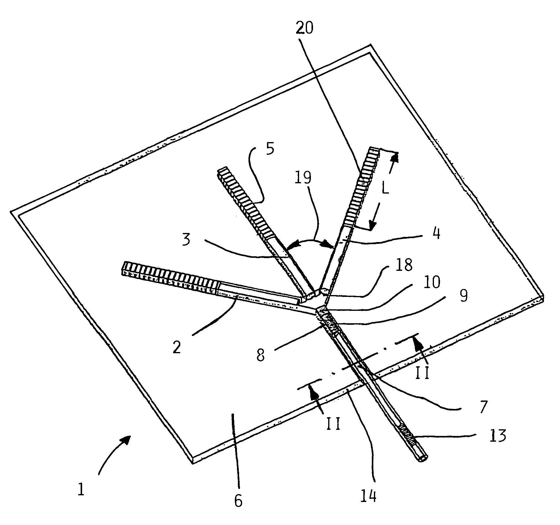
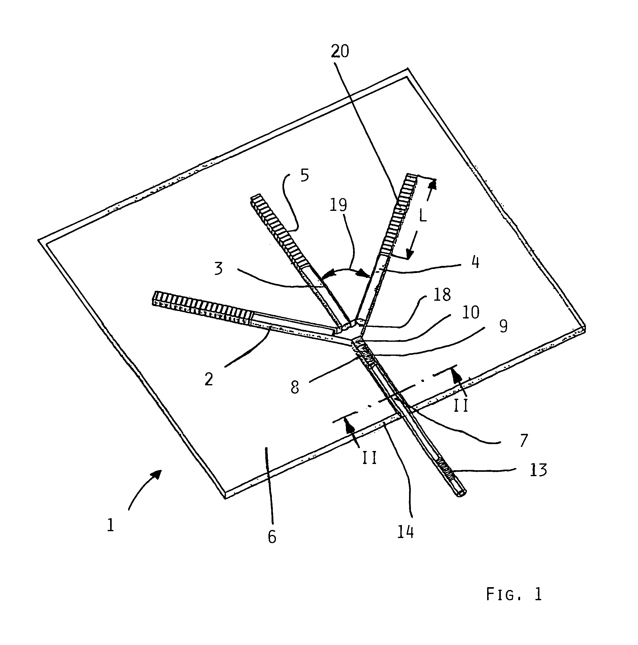
[0017]An optical strain gage 1 is illustrated in FIG. 1 of the drawing, which is embodied as a rosette for the biaxial strain measurement and which consists of three measuring waveguide sections 2, 3, 4 arranged next to one another and with impressed Bragg gratings 5, which are fed or supplied by an injecting or infeeding waveguide 7, of which the lightwave signals are transmitted through a beam spreading or dispersing element 8.

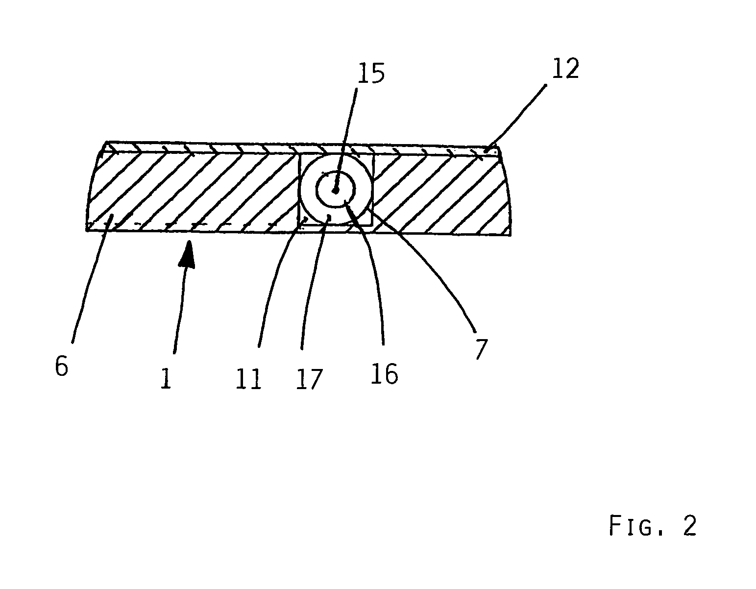
[0018]The light waveguides 2, 3, 4 are all embodied as linear sections and are embedded or led into a common support layer 6, which is embodied as a support film. In that regard, the light waveguide sections consist of an infeeding waveguide and three further transmitting sections of measuring waveguides 2, 3, 4 with preferably impressed Bragg gratings 5. For receiving the light waveguides 2, 3, 4, a thin support film 6 is provided, which preferably consists of a hard and elastic synthetic plastic, such as polyimide for example. The support film 6 may, howev...


PUM


Abstract

An optical strain gage (1) for multi-axis strain measurement includes at least two linear light waveguide sections (2, 3, 4) with Bragg gratings (5). These are arranged next to one another in a prescribed angle (19) of 90° or 45° on a support layer (6) and are supplied with lightwaves by a common infeeding waveguide section (7). All of the light waveguide sections(2, 3, 4, 7) are provided preferably linearly on the support layer (6), and a beam dispersion element (8) is arranged between the infeeding waveguide section (7) and the measuring waveguide sections (2, 3, 4) containing the Bragg grating (5).

Description

FIELD OF THE INVENTION[0001]The invention relates to an optical strain gage for detecting a multi-axis strain and to a method of producing such an optical strain gage.BACKGROUND INFORMATION[0002]Electrical strain gages are frequently utilized for the measurement-technology evaluation of forces or for the monitoring of mechanically loaded structural components. The strain gages detect the strain of structural elements impinged or acted on by force. Such electrical strain gages usually consist of photolithographically produced meander-shaped measuring grids of an electrical resistance material that is applied on a support film of synthetic plastic and is usually covered with a further synthetic plastic protective film for mechanical protection. These electrical strain gages are applied on a deformation body for the detection of a load-dependent strain and convert the strain, through a resistance variation of the measuring grid, into an electrical signal that is proportional to the str...

Claims


Application Information

Patent Timeline
IPC IPC(8): G02B6/34G02B6/00
CPCG01L1/246
Inventor HAASE, KARL-HEINZSCHMIDT, MICHAELBLIN, REGIS
Owner HOTTINGER BALDWIN MESSTECHNIK GMBH
Why Eureka
Try Eureka