

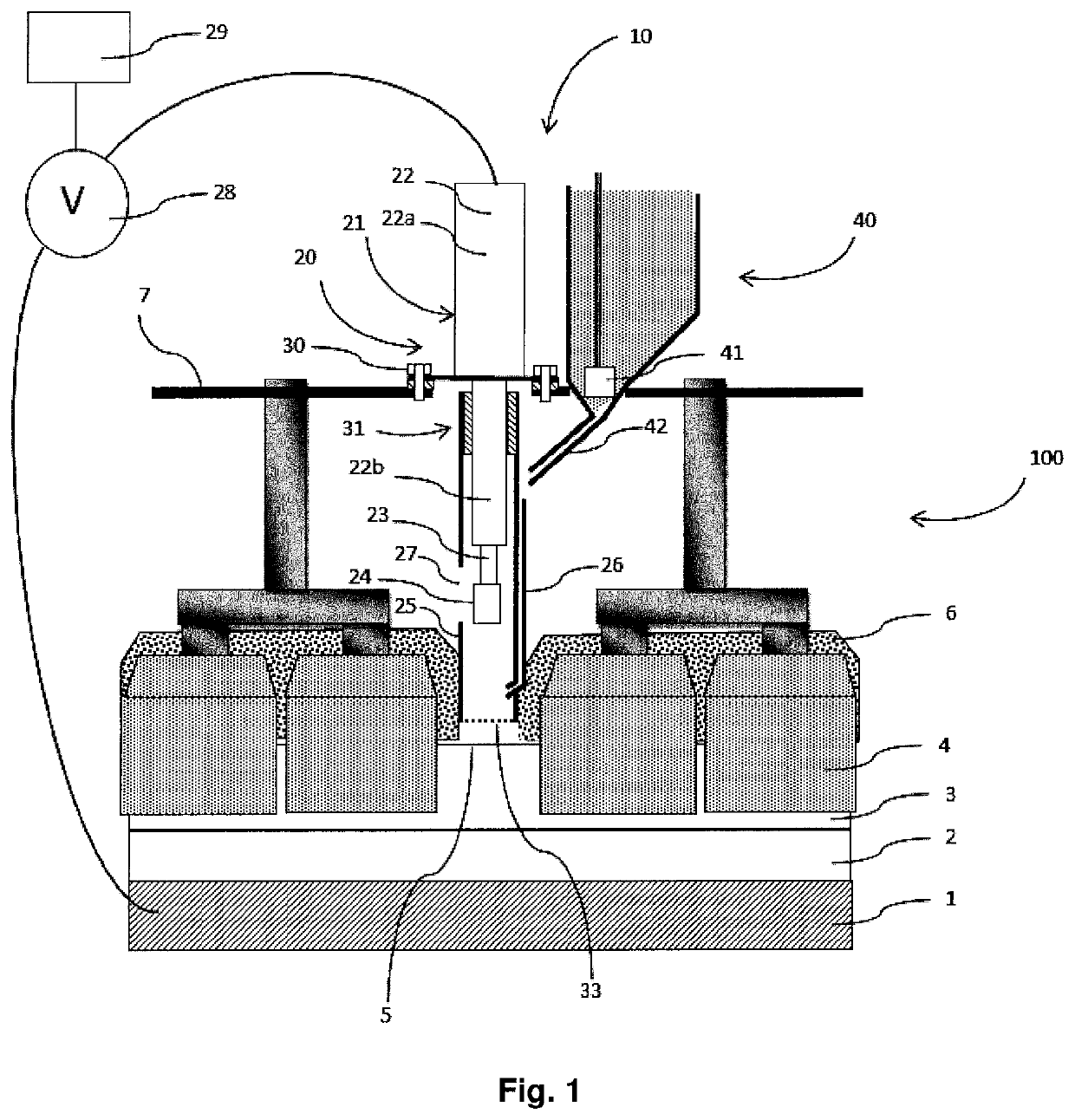
Drilling device comprising a tubular sheath secured to an actuator
a tubular sheath and actuator technology, applied in the direction of manufacturing tools, instruments, transportation and packaging, etc., can solve the problems of periodic collapse of powdery covering materials, permanent change in the composition of electrolyte baths, and impair the efficiency of covering, so as to limit the manufacturing cost of piercing devices and good durability
- Summary
- Abstract
- Description
- Claims
- Application Information
AI Technical Summary
Benefits of technology
Problems solved by technology
Method used
Image

Examples
second embodiment
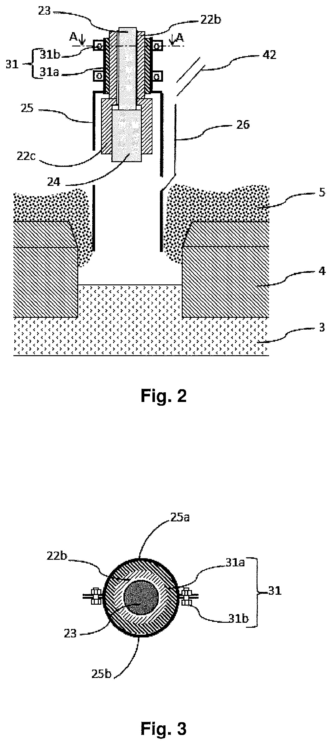
[0061]The second embodiment according to the invention shown in FIGS. 2 and 3 differs mainly from the embodiment shown in FIG. 1 in that the jack body 22 comprises a scraper 22c arranged as an extension of the guiding means 22b under the guiding means 22b and in that the electrically insulating fastener 31 between the tubular sheath 25 and the jack body 22 is formed at the lower end of the guiding means 22b.
[0062]The tubular sheath 25 is formed of two parts 25a and 25b assembled together. The electrically insulating fastener 31 is made by means of a sleeve 31a made of an electrically insulating material threaded around the guiding means 22b and bolts 31b making it possible to assemble and grip the two parts 25a, 25b of the tubular sheath 25 around the sleeve 31a and guiding means 22b.
[0063]The scraper 22c is formed of claws which rub against the surface of the piercing component 24 when the piercing component 24 moves towards the top position (shown in FIGS. 2 and 3) in order to k...
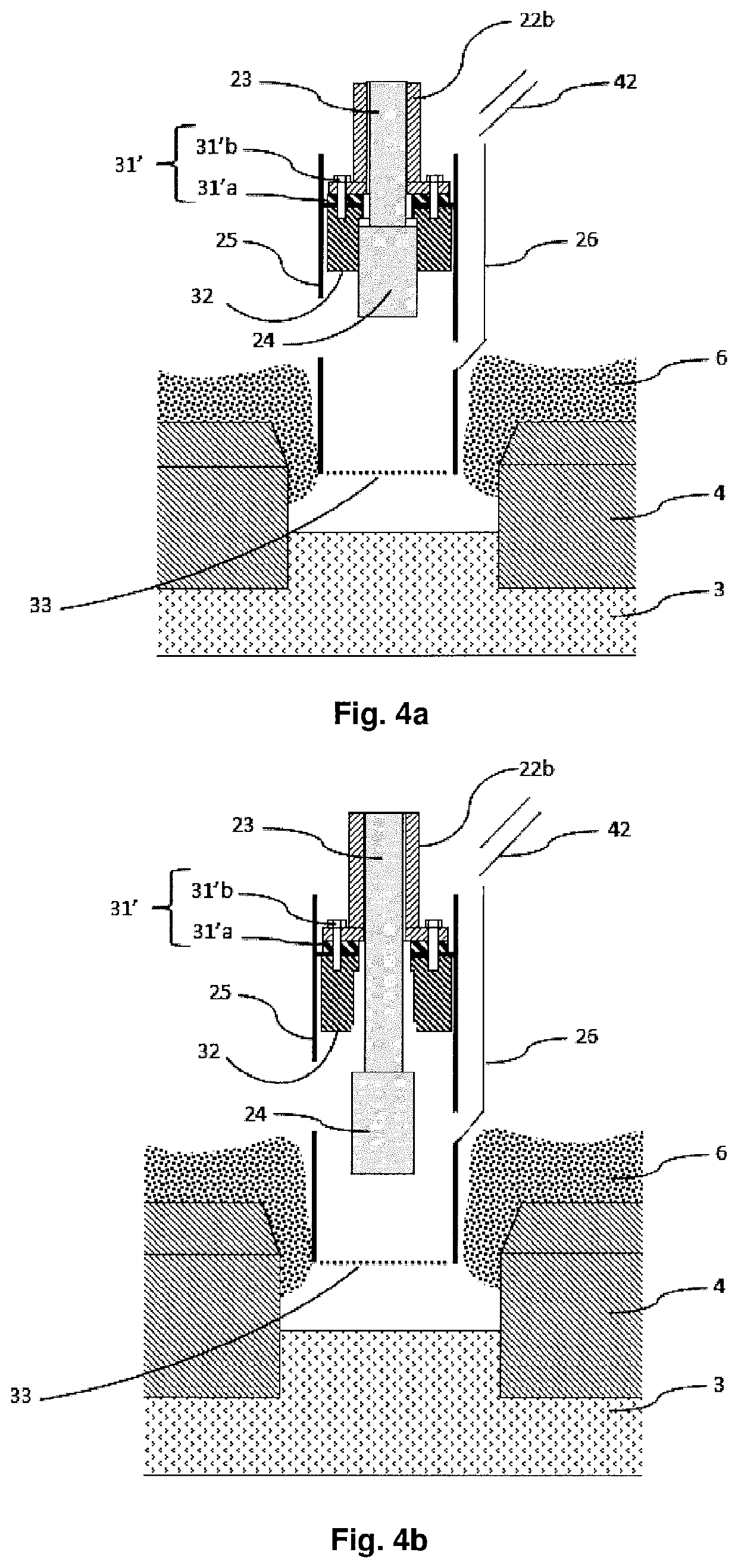
third embodiment
[0067]The scraper 32 is a constituent part of the tubular sheath 25 and is advantageously made of metal and more particularly of steel. It is therefore at the electric potential of the covering material 6 in which the tubular sheath 25 is partially embedded. The piercing component 24 rubs against the scraper 32 and touches it when the piercing component 24 is opposite the scraper 32, and in particular when the piercing component 24 is in the top position (as shown in FIG. 4a). Consequently, the piercing component 24 is at the electric potential of the covering material 6 when the piercing component 24 is opposite the scraper 32. The piercing component 24 regains a floating electric potential when the piercing component 24 is no longer opposite the scraper 32 (as shown in FIG. 4b), since the piercing component 24 and the rod 23, with a section typically lower than that of the piercing component 24, are then distant from the walls of the tubular sheath 25, and in particular from the s...
PUM
| Property | Measurement | Unit |
|---|---|---|
| temperature | aaaaa | aaaaa |
| temperature | aaaaa | aaaaa |
| electrically insulating | aaaaa | aaaaa |
Abstract
Description
Claims
Application Information