Safety structure for a railway line

Inactive Publication Date: 2012-02-16
ROOF SAFETY SYST
View PDF21 Cites 1 Cited by
  • Summary
  • Abstract
  • Description
  • Claims
  • Application Information

AI Technical Summary

Problems solved by technology

This means that the fitting of such fencing is a complicated matter which takes up a considerable amount of time.
The fitting and removal of fencing is a highly critical period because, at those times, the railway workers are not protected, and/or the railway traffic has to be halted completely.
This means that removal of the magnet and thus of the support of the rail is not possible by simply pulling thereon, that is to say applying a tensile

Method used


Image

  • Safety structure for a railway line
  • Safety structure for a railway line
  • Safety structure for a railway line

Examples


Example

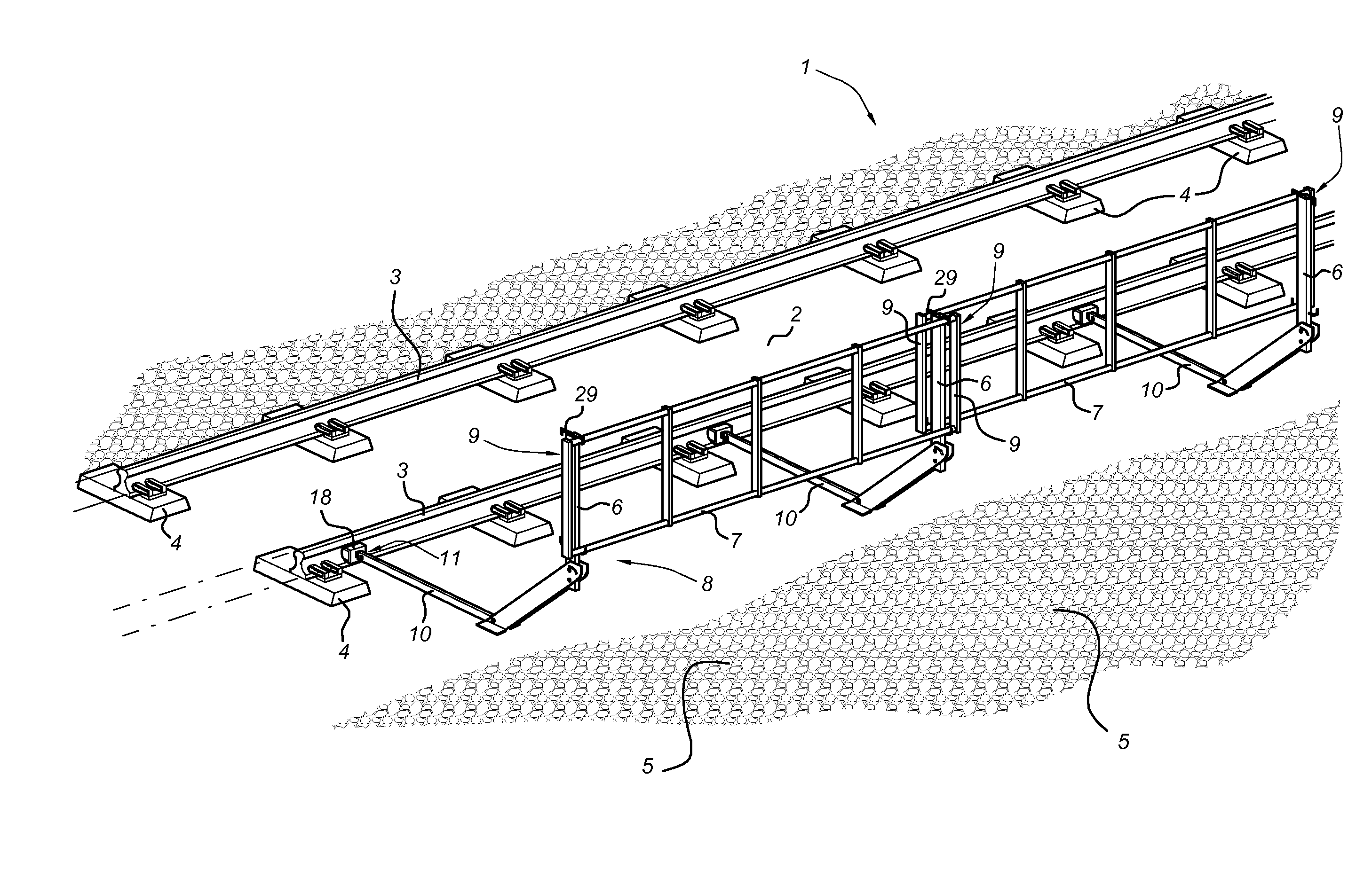
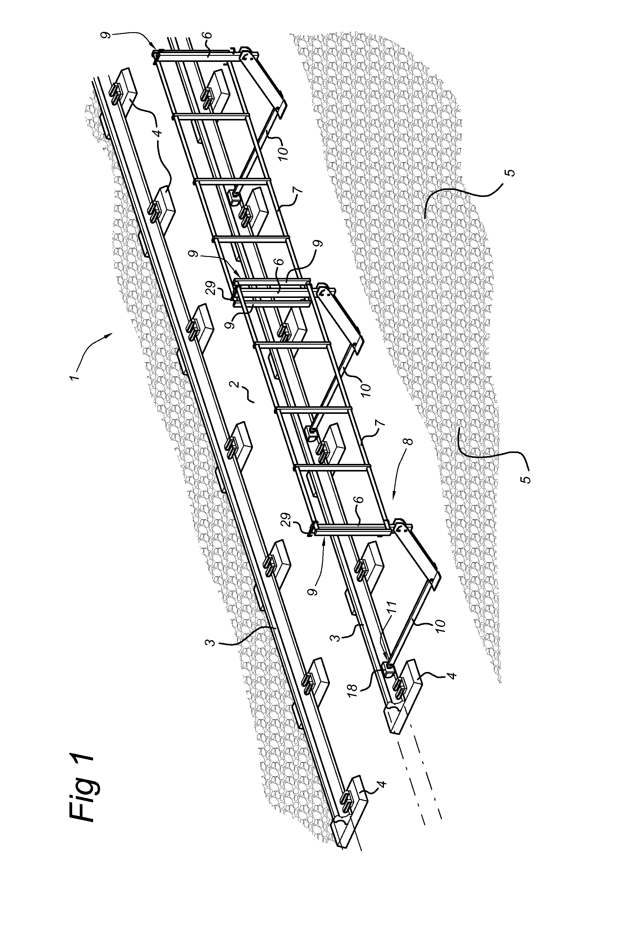
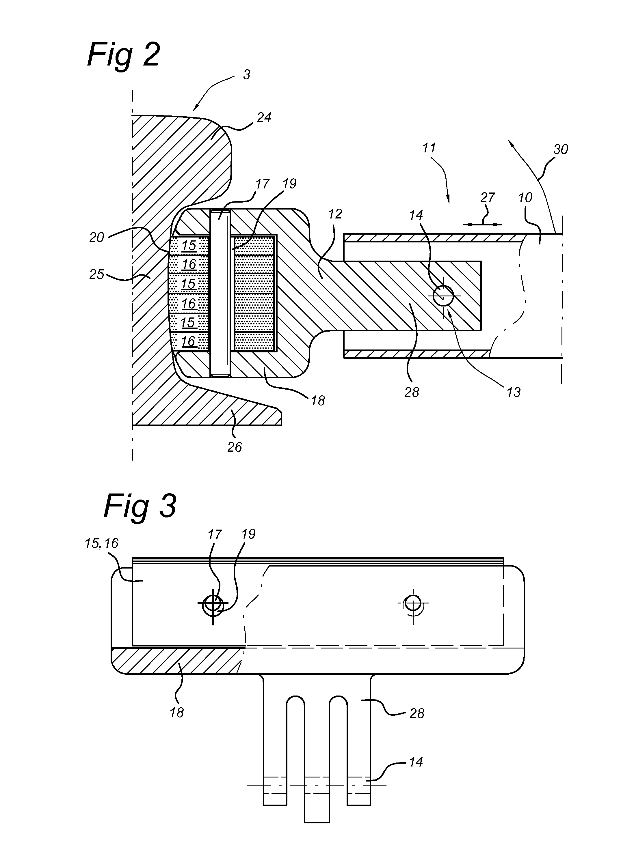
[0029]FIG. 1 shows a railway line consisting of a railway track 1 on which no work is being carried out. This railway track 1 comprises a bed 2 with two spaced-apart rails 3 arranged thereon which are connected to one another via sleepers 4. Reference numeral 5 denotes the zone situated next to the railway track 1. This may be a road or another civilian structure, but will generally be a further railway track, with maintenance having to be carried out on said railway track 5 (not shown). Rail 3 consists of a head 24, web 25 and foot 26.

[0030]If the railway track 1 remains in use, the safety of the workers must be ensured under all circumstances. To this end, a fencing 9 consisting of longitudinal pipes 7 coupled to posts 6 is provided to form the fencing 9. The posts 6 are connected to supports 10 by means of hinges 22 and 23 which are to be described below with reference to FIGS. 4 and 5. The supports 10 are attached to the web 25 of rail 3 by means of permanent magnets, as can be ...


PUM

PropertyMeasurementUnit
Lengthaaaaaaaaaa
Lengthaaaaaaaaaa
Lengthaaaaaaaaaa

Abstract

Safety structure for protecting a construction including a rail extending along the construction, includes a fencing supported on supports resting on the track bed. These supports are connected to a rail. The connection is effected by a magnetic force. At their free ends, the supports are provided with permanent magnets having a shape such that they can be brought into engagement with a surface part of the rail. Due to the significant length of the supports, it is possible to apply a great torque to the magnets when the other end is engaged, that is to say that end which is turned away from the permanent magnets, as a result of which the magnet slides away along the web and can be detached therefrom. The magnet may include a number of magnets stacked on top of one another. The magnet may be slightly displaceable with respect to the support.

Description

CROSS REFERENCE TO RELATED APPLICATIONS[0001]This application is a continuation-in-part of copending application Ser. No. 13 / 262,090 filed on Sep. 29, 2011; which is the 35 U.S.C. 371 national stage of International application PCT / NL10 / 50159 filed on Mar. 29, 2010; which claims priority to Netherlands application 2002682 filed Mar. 30, 2009. The entire contents of each of the above-identified applications are hereby incorporated by reference.BACKGROUND OF THE INVENTION[0002]The present invention relates to a safety structure according to the preamble of claim 1.[0003]A structure of this type is generally known in the state of the art. Examples which may be mentioned include FR 2,904,836, NL 1,030,956 and GB 2,333,795. All these structures are configured to connect the support to a rail of the railway track which is still present, due to the fact that when work is being carried out on double or multiple tracks, one railway track will generally be worked on while the other railway tr...

Claims


Application Information

Patent Timeline
IPC IPC(8): B61K13/00B23P19/00H01F7/04E04H17/20H01F7/02
CPCE01B26/005Y10T29/49815H01F7/0252
Inventor BIESBROUCK, GERARDUS MAJELLABAKKER, JOHANNES ANTONIUS
Owner ROOF SAFETY SYST
Why Eureka
Try Eureka