Central heating radiators

Inactive Publication Date: 2003-08-19
OYSTERTEC
View PDF13 Cites 7 Cited by
  • Summary
  • Abstract
  • Description
  • Claims
  • Application Information

AI Technical Summary

Benefits of technology

Preferably the liquid inlet and the liquid outlet are located at or near the top and bottom respectively of one side of the radiator panel. Conventionally, liquid flow and return connections to a radiator panel are made to opposite ends of a horizontal edge of a radiator. By arranging the liquid flow to be to and from a common vertical edge of the radiator, a considerable length of pipe may be eliminated, particularly in

Problems solved by technology

Although this minimises the amount of unsightly, exposed pipework, it can cause problems in that water fed to the radiator tends to "short circuit" between the flow and return connections along the lower edge of the radiator, causing poor or uneven heating of the radiator.
This dirt and dust is unsightly and unhygienic and can soil the decoration on the wall around the radiator.
However, cleaning the narrow space behind the radiators is difficult.
In addition, redecorating the wall behind or around a radiator, or repainting the back of a radiator, is also difficult.
Although acc

Method used


Image

  • Central heating radiators
  • Central heating radiators
  • Central heating radiators

Examples


Embodiment Construction

An embodiment of the present invention will now be described, by way of example only and with reference to the accompanying drawings.

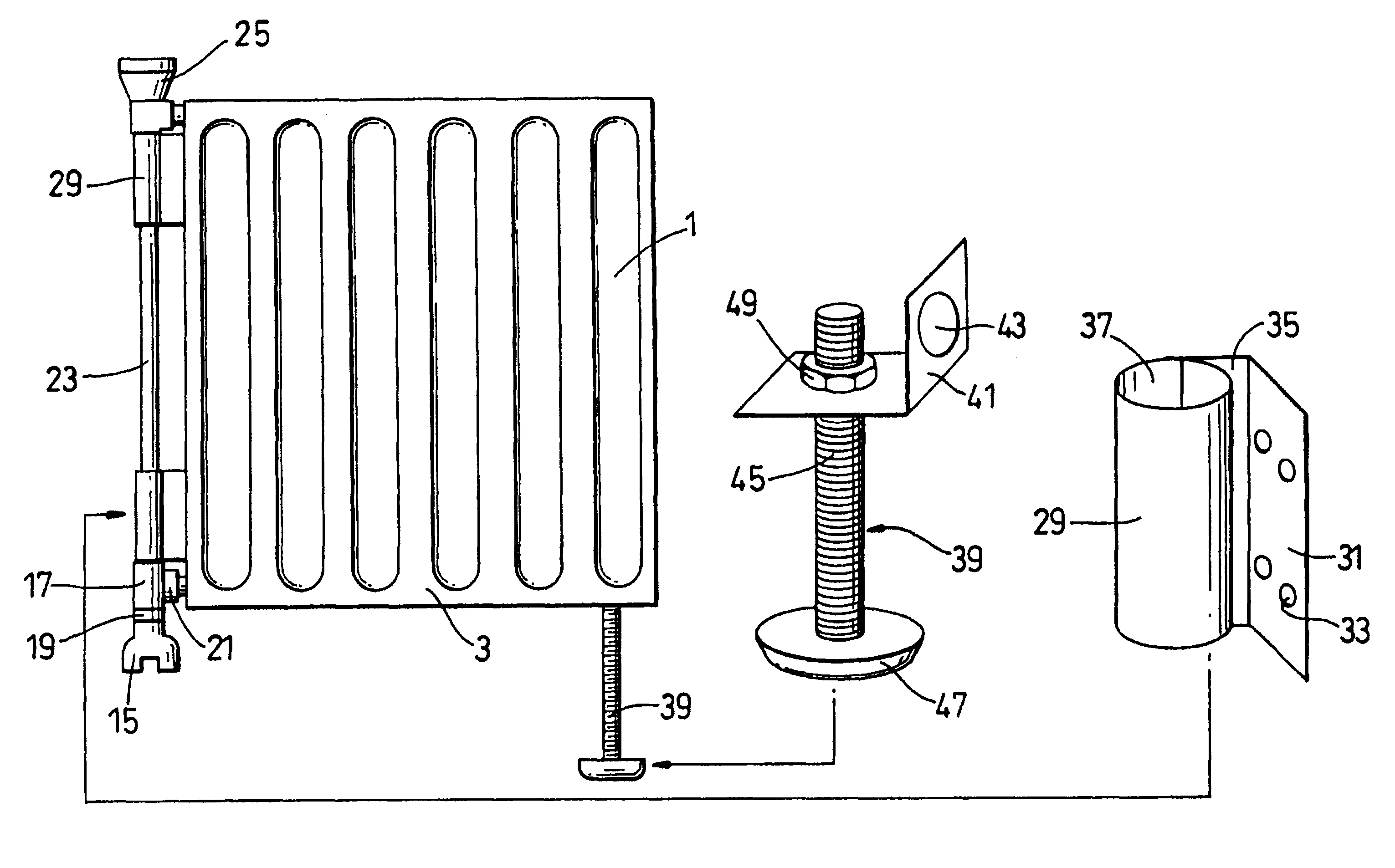
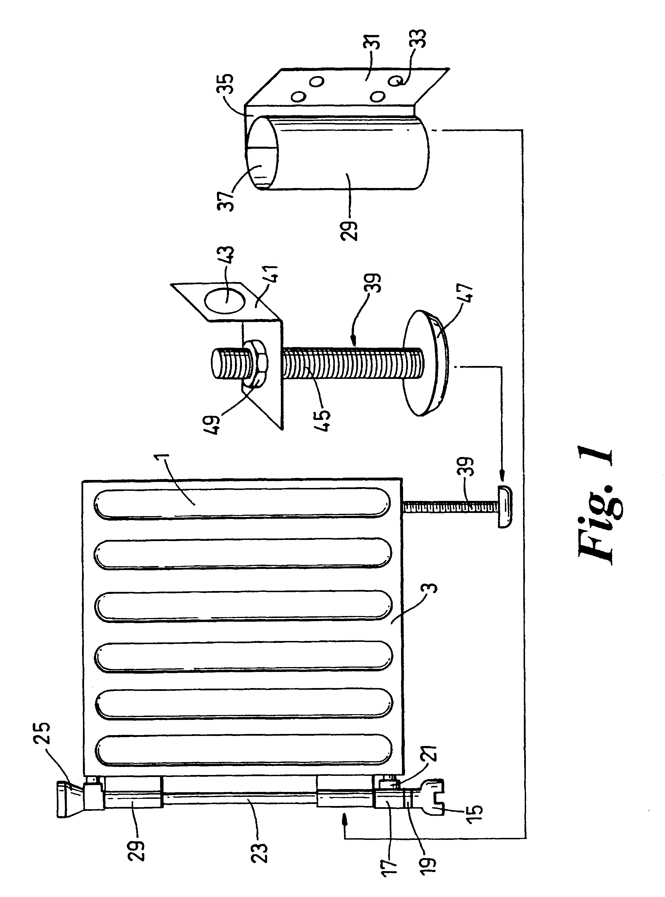
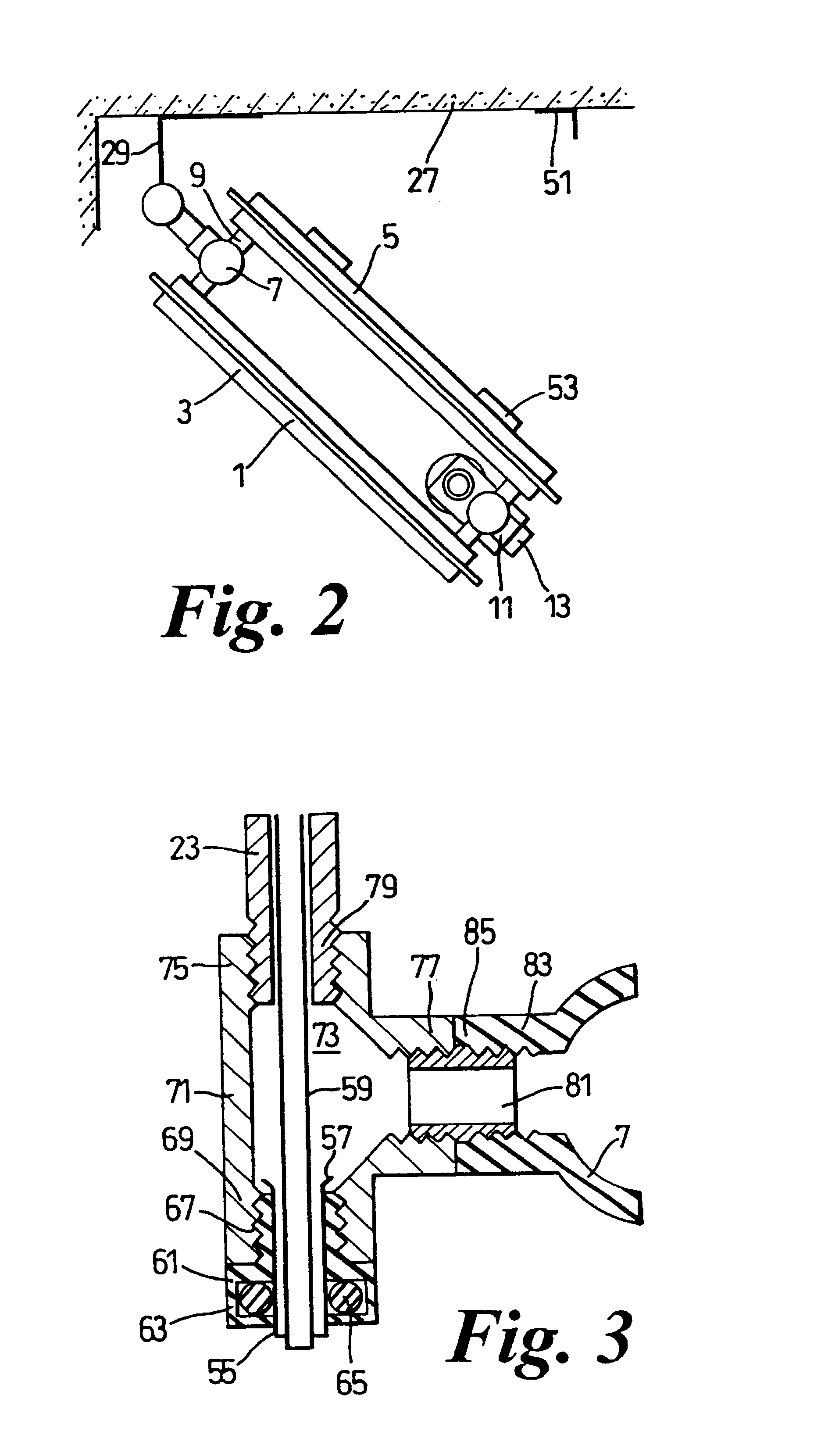
A central heating radiator assembly comprises a radiator panel 1 which, in this case, comprises two sub-panels 3, 5 interconnected by two pairs of upper and lower radiator bosses. Each radiator boss 7 is connected to each panel 3, 5 by means of connecting arms 9. Each boss 7 is also provided with a boss inlet 11. On the right hand side of radiator panel 1, as seen in FIG. 1 the two boss inlets 11 are closed by radiator plugs 13. The bosses on the left hand side of the panel form part of a water inlet for the panel (upper boss) and a water outlet for the panel (lower boss).

Located at the lower left hand corner of panel 1 is a standard flow and return valve 15 by means of which heating water may be led to the panel 1 and water, exiting from panel 1, may be led away from the radiator. Valve 15 is connected to a T-junction connector 17 by means of a plug 1...


PUM


Abstract

A central heating radiator assembly comprises a radiator panel (1) having a liquid inlet (25, 7) and liquid outlet (7, 21). Attachment means (29) are for attaching the panel to a wall (27) and pivot means (29) enable the panel to be rotated away from the wall about an upright axis. The invention also provides a method of installing a central heating radiator assembly and a kit of parts for such installation.

Description

This invention relates to central heating radiators and, more particularly, to the connection of a central heating radiator to its liquid flow and return pipes.BACKGROUND TO THE INVENTIONCentral heating radiators are conventionally mounted adjacent to a wall by hanging them from brackets secured to the wall. The radiator is then plumbed into the heating system by connecting flow and return pipes to apertures in the radiator. The flow and return pipes are usually connected to apertures located at opposite ends of the lower edge of the radiator. Although this minimises the amount of unsightly, exposed pipework, it can cause problems in that water fed to the radiator tends to "short circuit" between the flow and return connections along the lower edge of the radiator, causing poor or uneven heating of the radiator.Dirt and dust tends to build up in the space between the radiator and the wall as a result of convection currents of air flowing between the radiator and wall when the radiat...

Claims


Application Information

Patent Timeline
IPC IPC(8): F24D19/00F24D19/02
CPCF24D19/02F24D19/0209F24D19/0223F24D19/023F24D19/0236F24D19/0293F24D2220/2054
Inventor DAVIDSON, PAUL ANTHONY
Owner OYSTERTEC
Why Eureka
Try Eureka