Safety structure for a railway line

a safety structure and railway line technology, applied in the field of safety structures, can solve the problems of affecting the safety of railway lines, and requiring complete stoppage of traffic, so as to achieve the effect of improving the safety structure, quick and simple manner, and fitting and removing

Active Publication Date: 2017-01-03
RSS HLDG BV
View PDF23 Cites 1 Cited by
  • Summary
  • Abstract
  • Description
  • Claims
  • Application Information

AI Technical Summary

Benefits of technology

[0008]It is an object of the present invention to provide an improved safety structure which can be fitted and removed in a quick and simple manner. In addition, it is an object of the present invention to provide a safety structure which can be used under all kinds of circumstances, that is to say both with structures using sleepers on a gravel bed and other kinds of structures (for example those where the sleepers are (partly) cast in or attached to a concrete slab).
[0012]This means that removal of the magnet and thus of the support of the rail is not possible by simply pulling thereon, that is to say applying a tensile force on the support in a direction at right angles to the longitudinal extension of the web. However, it is possible to release the connection between the support and the rail in a simple manner by tilting the end of the support upwards, away from the rail. Such a tilting movement will cause the magnet to move along the web and subsequently along the foot of the rail and will then cause the connection between the rail and the permanent magnet to be released by a sliding movement. This type of disconnection by a sliding movement can be achieved in a relatively simple manner. In addition, the support has a considerable length, so that the application of a force near its free end results in a significant torque being applied to the rail.
[0015]According to a further advantageous embodiment, the magnet can be displaced slightly with respect to the support. This displacement is relatively small, but makes it possible to compensate for differences in height resulting from inaccuracies, such as for example differences in height due to the presence of the gravel bed. According to a further embodiment, with the structure which is fitted with a number of magnet sections, these magnet sections can also be displaced with respect to one another. This is preferably achieved by means of a fork-like part in which said magnet or magnet sections are accommodated.
[0016]According to a further advantageous embodiment, the supports are hingedly connected to one another by means of posts. Pipes are in turn attached to these posts, thus forming the fencing. These posts can be folded in with the supports, producing a compact structure which can easily be removed and transported.
[0017]According to a particular embodiment of the present invention, the head end part comprising the magnet (magnet sections) is the only part of the support which is in contact with the rail. According to a particular embodiment of the present invention, the support is designed such that it can rest on a sleeper. By resting the support in this way, it can be ensured in the case of a series of supports that these are always exactly at the same level, as a result of which the fencing can be accurately adjusted. This prevents any irregularities in the gravel bed from causing an irregular positioning of the fencing.

Problems solved by technology

This means that the fitting of such fencing is a complicated matter which takes up a considerable amount of time.
The fitting and removal of fencing is a highly critical period because, at those times, the railway workers are not protected, and / or the railway traffic has to be halted completely.

Method used


Image

  • Safety structure for a railway line
  • Safety structure for a railway line
  • Safety structure for a railway line

Examples


Embodiment Construction

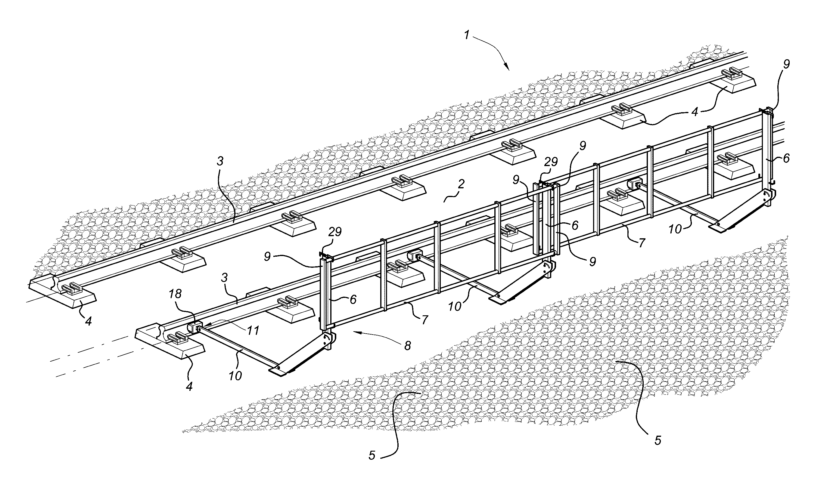
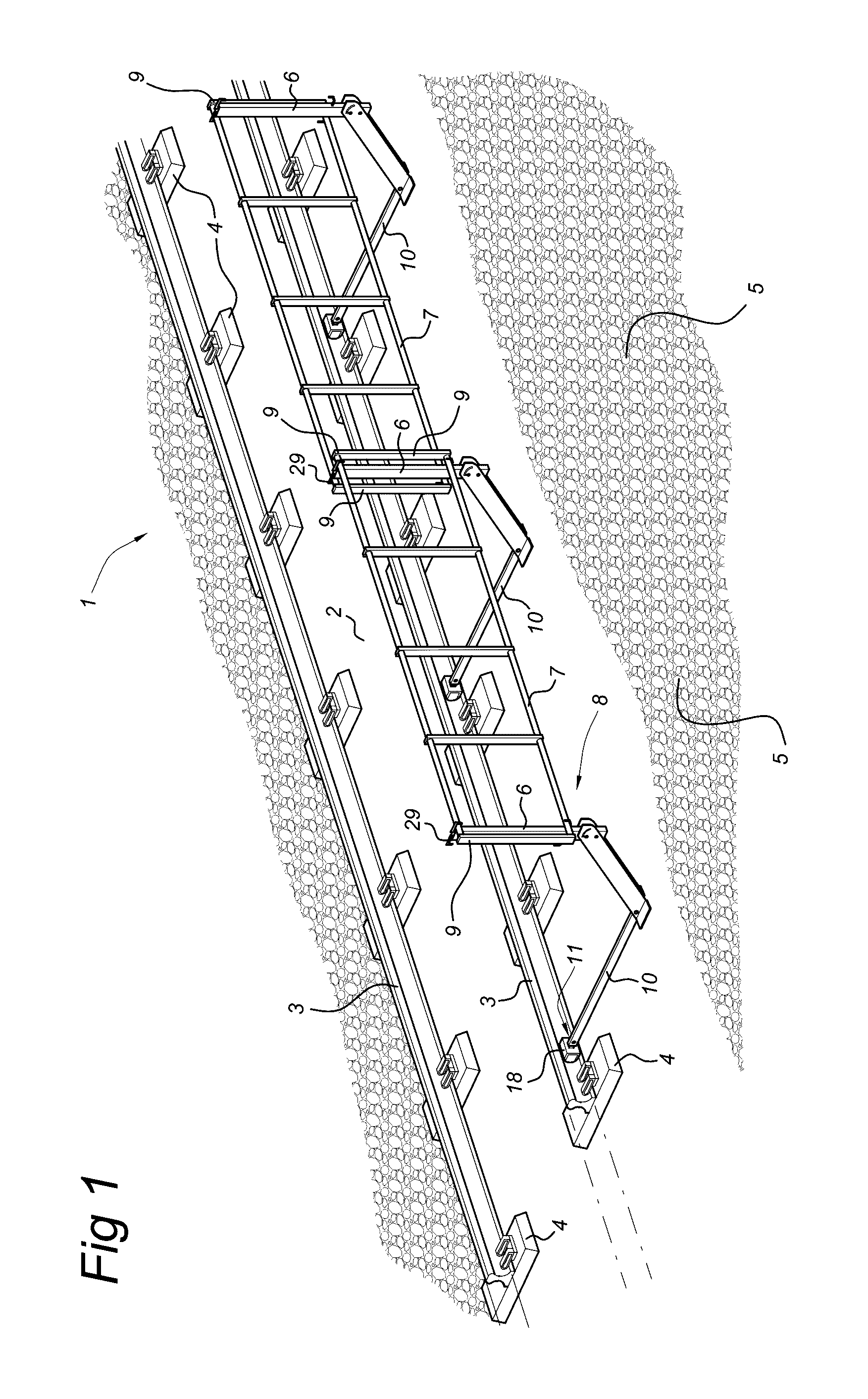
[0027]FIG. 1 shows a railway line consisting of a railway track 1 on which no work is being carried out. This railway track 1 comprises a bed 2 with two spaced-apart rails 3 arranged thereon which are connected to one another via sleepers 4. Reference numeral 5 denotes the zone situated next to the railway track 1. This may be a road or another civilian structure, but will generally be a further railway track, with maintenance having to be carried out on said railway track 5 (not shown). Rail 3 consists of a head 24, web 25 and foot 26.

[0028]If the railway track 1 remains in use, the safety of the workers must be ensured under all circumstances. To this end, a fencing 9 consisting of longitudinal pipes 7 coupled to posts 6 is provided to form the fencing 9. The posts 6 are connected to supports 10 by means of hinges 22 and 23 which are to be described below with reference to FIGS. 4 and 5. The supports 10 are attached to the web 25 of rail 3 by means of permanent magnets, as can be ...


PUM

PropertyMeasurementUnit
tensile forcesaaaaaaaaaa
diameteraaaaaaaaaa
shapeaaaaaaaaaa

Abstract

Safety structure for protecting a railway line includes a fencing on supports resting on the track bed. These supports are connected to a rail of a railway line. The connection is effected by magnetic force. At their free ends, the supports have permanent magnets having a shape allowing them to engage the web of a rail. Due to the significant length of the supports, it is possible to apply a great torque to the magnets when the other end is engaged, that is to say that end which is turned away from the permanent magnets, as a result of which the magnet slides away along the web and can be detached therefrom. The magnet may consist of a number of magnets stacked on top of one another. The magnet is preferably arranged so as to be slightly displaceable with respect to the support to provide compensation for an uneven surface.

Description

BACKGROUND OF THE INVENTION[0001]Field of the Invention[0002]The present invention relates to a safety structure for protecting a construction including a rail extending along the construction.[0003]Description of the Related Art[0004]A structure of this type is generally known in the state of the art. Examples which may be mentioned include FR 2,904,836, NL 1,030,956 and GB 2,333,795. All these structures are configured to connect the support to a rail of the railway track which is still present, due to the fact that when work is being carried out on double or multiple tracks, one railway track will generally be worked on while the other railway track will remain in use. Therefore, the railway workers will have to be protected. The only fixed points on such a railway track are the rails and sleepers. Therefore, the above-described prior art proposes a structure which engages with the rail foot or the centre sections of the rail, since the head of the rail has to remain clear for an...

Claims


Application Information

Patent Timeline
Patent Type & Authority Patents(United States)
IPC IPC(8): E01B5/18E01B17/00E01B26/00H01F7/02
CPCE01B26/005H01F7/0252Y10T29/49815
Inventor BIESBROUCK, GERARDUS MAJELLABAKKER, JOHANNES ANTONIUS
Owner RSS HLDG BV
Why Eureka
Try Eureka