
Installation and method for conditioning a sheet of moulding material

Inactive Publication Date: 2005-05-24
MIXT COMPOSITES RECYCLABLES
View PDF7 Cites 0 Cited by
  • Summary
  • Abstract
  • Description
  • Claims
  • Application Information

AI Technical Summary

Benefits of technology

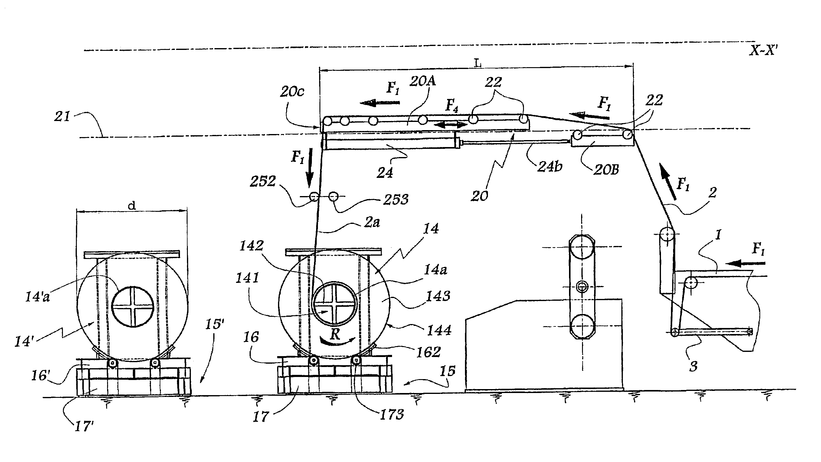
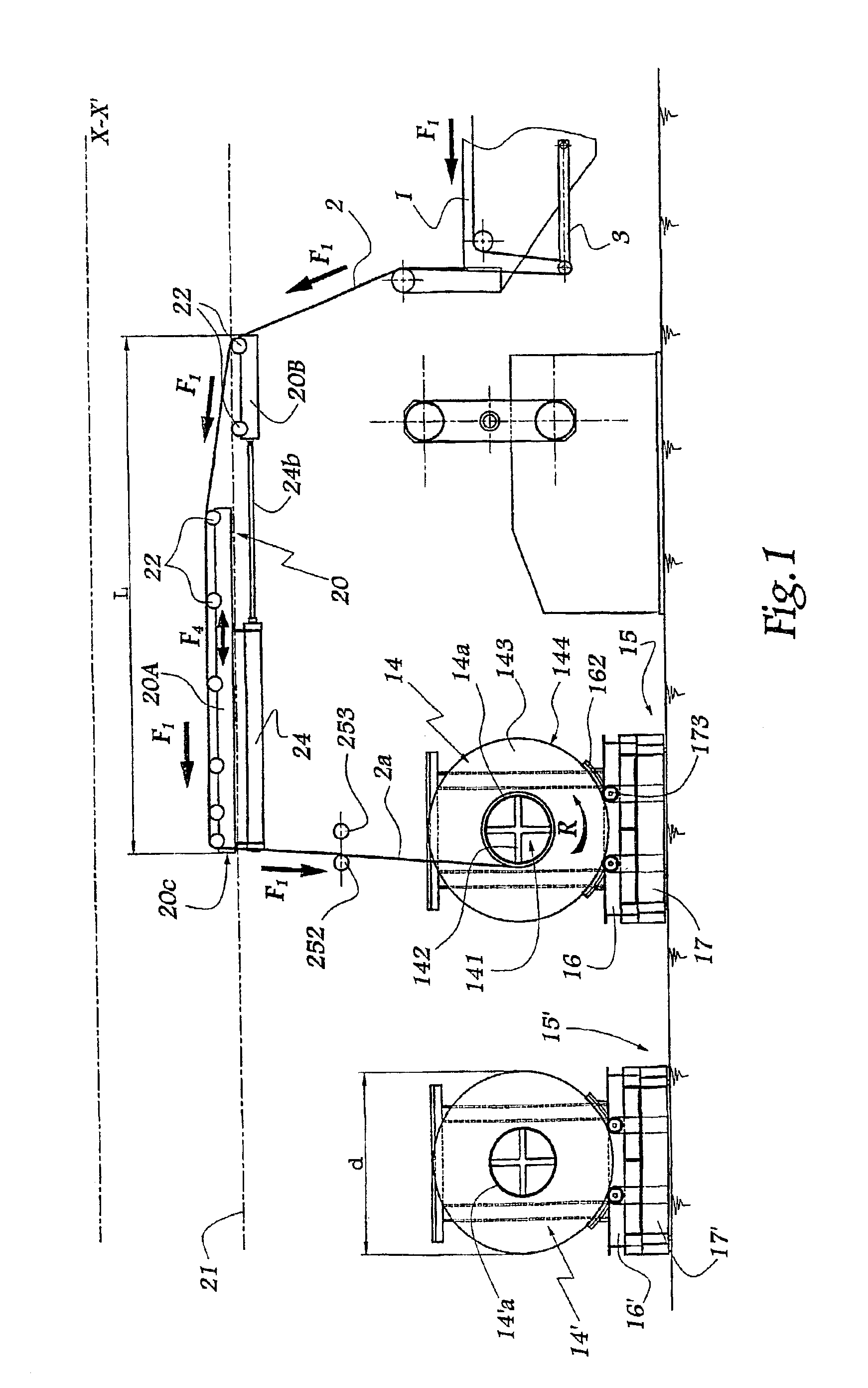
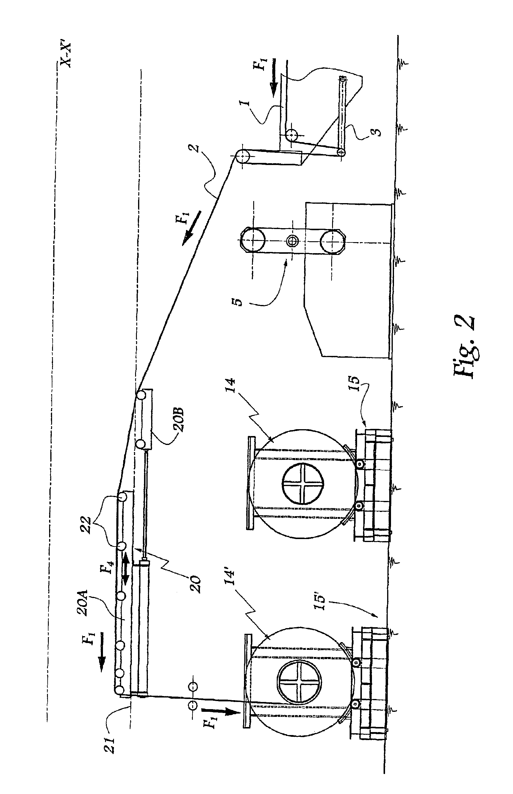
[0010]Thanks to the invention, the use of two successive locations makes it possible to provide, for each location, adapted means for supporting and driving the web of moulding material, while the carriage makes it possible to take the sheet of moulding material up to each of the coils respectively installed in each of these locations. The bipartite nature of the carriage of the invention makes it possible to vary its length parallel to the horizontal direction of advance of the sheet. It is thus possible to provide a compact configuration of this carriage, for example when it is not used, and an extended position which allows it to guide the sheet of moulding material over a relatively considerable length. The conditions of support of the sheet at the exit of the moulding material producing machine may thus be optimized.
[0016]The carriage is adapted to be displaced towards a standby position where it does not interfere with the path of the sheet. This aspect of the invention makes it possible to use an SMC producing machine both to produce coils of SMC of considerable weight, greater than 1000 kg, and coils of SMC of the order of 300 to 700 kg, such as known previously.
[0017]Each coil is mounted in a principal chassis in which it is adapted to rest, by the peripheral edges of its end plates, on blocking shoes, while the principal chassis is adapted to be placed on an auxiliary chassis equipped with rollers adapted to lift the afore-mentioned edges with respect to the shoes when the principal chassis is placed on the auxiliary chassis. The use of these two chassis makes it possible to provide a blocking by default of a coil inside the principal chassis thanks to the use of the shoes, such blocking being eliminated when the coil and the principal chassis are placed on the auxiliary chassis, the idly mounted rollers making it possible to support the end plates of the coil with a possibility of rotation.
[0018]The auxiliary chassis is equipped with wheels allowing it to slide in a direction substantially perpendicular to the direction of advance of the sheet. This transverse access makes it possible to carry out the operations of positioning and of evacuation of the coils in masked time.

Problems solved by technology

However, for at least certain applications, it is necessary to provide the use of large-capacity coils, such coils not being able to be manipulated by a system incorporating rocker, due to their weight and dimensions.

Method used


Image

  • Installation and method for conditioning a sheet of moulding material
  • Installation and method for conditioning a sheet of moulding material
  • Installation and method for conditioning a sheet of moulding material

Examples


Embodiment Construction

[0038]The installation according to the invention is arranged at the exit of a machine 1 for producing composite moulding material of SMC type, in the form of a sheet 2 circulating along a path represented by arrows F1 in the Figures. The machine 1 is equipped with a “jumping jack” element 3 for compensating the variations in length and speed of advance of the sheet 2.

[0039]As is more particularly visible in FIG. 8, the sheet 2 may be wound over the mandrel 4a or 4′a of coils 4 and 4′ supported by the arms of a rocker 5 disposed opposite the exit zone of the machine 1. In the configuration shown in FIG. 8, the sheet 2 is in the course of being wound on the coil 4, while coil 4′ may be either loaded on the rocker 5, or unloaded therefrom before being stored on a transport pallet 6 disposed in the vicinity. This use of the machine 1 corresponds to the known state of the art.

[0040]When the coils 14 and 14′ of large diameter d are to be used, particularly for winding the sheet 2 in quan...


PUM

PropertyMeasurementUnit
Currentaaaaaaaaaa
Digital informationaaaaaaaaaa

Abstract

An installation for winding sheets of molding materials exiting a machine wherein at least two coil devices are provided at space locations horizontally with respect to an exit of the machine, and wherein the sheet material is directed to the coils by way of a horizontally movable carriage including a main frame and a secondary frame, which is adjustable horizontally relative to the main frame, and which carriage is movable horizontally to direct the sheet material to a selected one of the at least two coils.

Description

BACKGROUND OF THE INVENTION[0001]1. Field of the Invention[0002]The invention relates to an installation and to a method for conditioning a sheet of moulding material on coils at the exit of a machine for producing a moulding material in sheet form.[0003]2. Brief Description of the Related Art[0004]Such a material, commonly called “SMC” (Sheet Moulding Compound) is produced continuously on a machine which may be of type known from FR-A-2 778 360 or of any other type. Such a machine functions without interruption and a system must be provided for conditioning the sheet of SMC produced, this system being compatible with the speed of advance of the sheet at the exit of the machine. When coils adapted to receive about 300 to 700 kg of material are used, it is possible to employ a system incorporating rocker provided with two mandrels supporting the coils, the material being alternately wound on each of these mandrels.[0005]However, for at least certain applications, it is necessary to p...

Claims


Application Information

Patent Timeline
IPC IPC(8): B65H19/26B65H19/30B65H19/22
CPCB65H19/22B65H19/26B65H19/30B65H2405/422B65H2301/41745B65H2301/41896
Inventor GAY, JEAN-LOUISFOUR, CHRISTIAN
Owner MIXT COMPOSITES RECYCLABLES
Learn More