Electric lock for doors

a technology for electric locks and doors, applied in the direction of building locks, construction, fastening means, etc., can solve the problems of inability to operate properly, complex structure, and high production cost of conventional electric locks, so as to avoid dust fals, reduce production cost, and simplify the effect of structur

Active Publication Date: 2017-07-11
LIAO LI SHIH
View PDF9 Cites 10 Cited by
  • Summary
  • Abstract
  • Description
  • Claims
  • Application Information

AI Technical Summary

Benefits of technology

[0006]The primary object of the present invention is to provide an electric lock for doors with simple structure and low rate of malfunction, and one that needs small currents for initiating with no need of PCB control system.
[0011]The present invention further has inclined surfaces on the inner side of both ends of the side wall near the opening to ensure the first and second catch to turn outside smoothly, and a cover disposed on the housing to avoid dust falling in. Additionally, the present invention includes a control system that can control the operation of the driving device under either electrically connected or disconnected status.
[0012]With the end of the second inner arm partially overlaps the end of the first inner arm, the holding surface of the blocking element would block the rear of the first catch to stop it from turning and thus stop the second catch as well when the blocking element is in the closing position. Consequently the latch is locked up in the hedge formed by the first and second catch, achieving the purpose of locking up. When the blocking element is in the opening position, the holding surface thereof leaves the blocking position and the blocking against the first catch is eliminated, enabling the turning of the first catch and the second catch as well, therefore unlocking the latch and achieving the purpose of unlocking. With the disclosed structures, the present invention only needs to control the first catch with one blocking element for operation, which has advantages of simpler structure and smaller volume comparing with a conventional lock; also, it saves energy since it only needs to control the first catch for operation.

Problems solved by technology

Furthermore, the conventional electric locks have defects as following.
Firstly, with the structures of two control systems, it needs two blocking elements to stop the catches from turning to lock up the latch.
Such structure is complicated and needs higher costs for production.
Also, the two blocking elements need to be operated synchronously; if one of which is malfunctioned, the lock would not be able to operate properly.
Secondly, such electric locks usually need higher currents for the solenoid valve to initialize the operation.
To avoid the solenoid valve to be overheated, PCB control devices are applied; however, PCB control devices are not durable as the electric locks are, which increases the risks of the locks.

Method used


Image

  • Electric lock for doors
  • Electric lock for doors
  • Electric lock for doors

Examples


Embodiment Construction

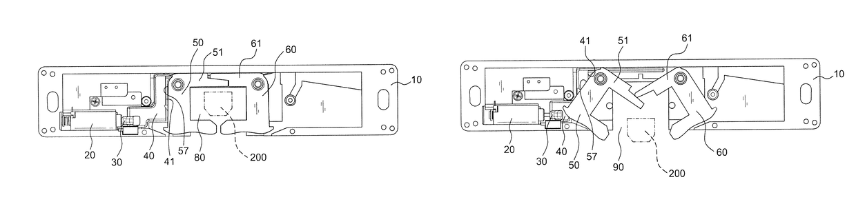
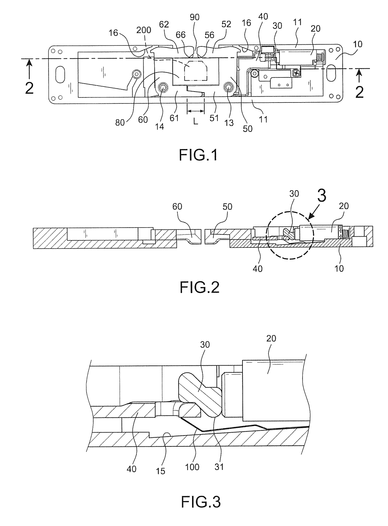
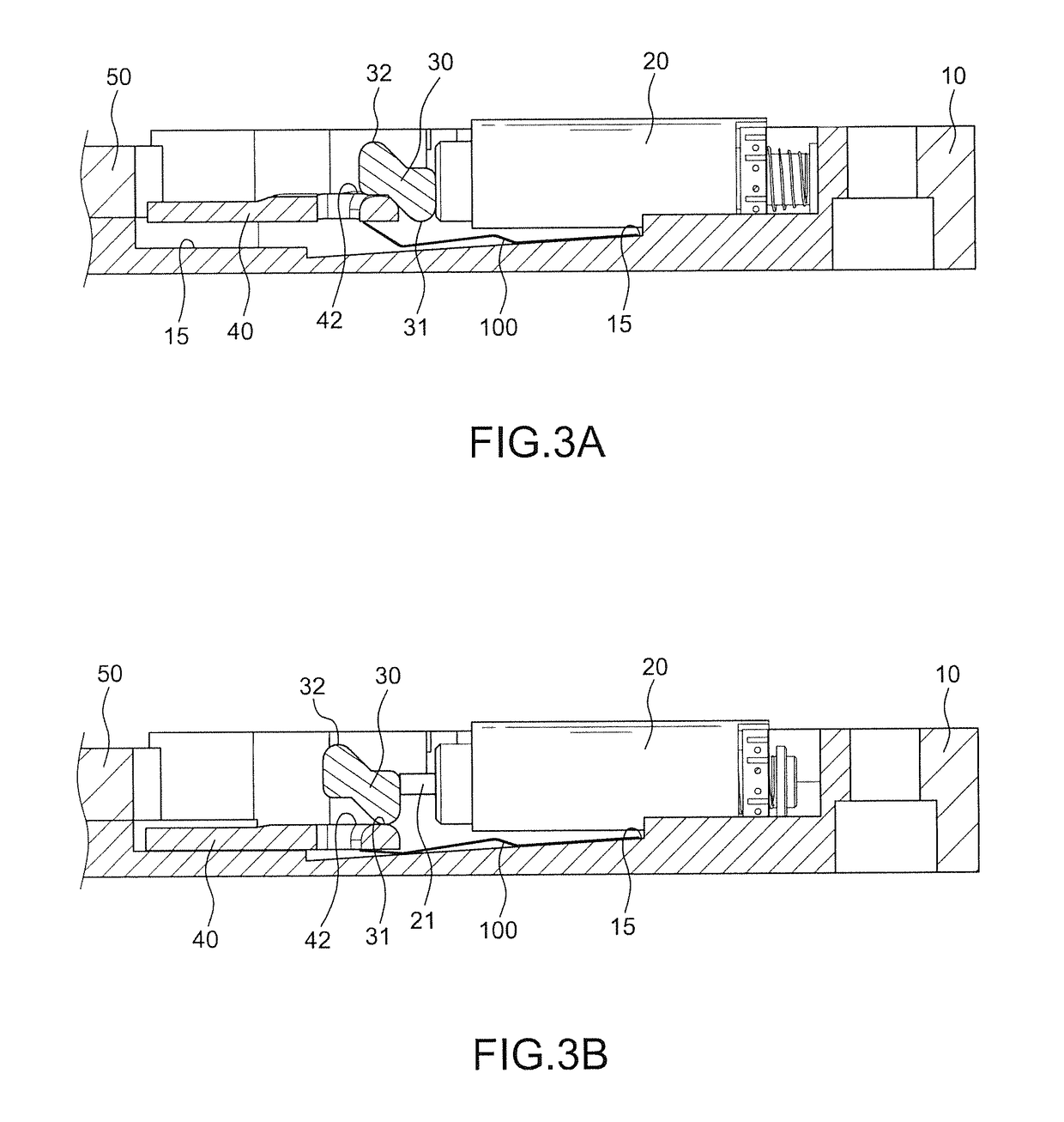
[0026]Referring to FIGS. 1, 6 and 7, the present invention comprises a housing 10, a driving device 20, a moving block 30, a blocking element 40, a first catch 50, a second catch 60, and a cover 70.

[0027]The housing 10 has a side wall 11 surrounding, on which an opening 90 is arranged for a latch 200 to enter; a first column 13 and a second column 14 are arranged symmetrically inside the housing 10 near the inner corners of the opening 90. The cover 70 is disposed on the housing 10 to avoid dust falling in and affect the operation. The first catch 50 has a first inner arm 51, a first outer arm 52, and a first positioning hole 53; near the rim of the first positioning hole 53 a first fillister 54 is arranged. The second catch 60 has a second inner arm 61, a second outer arm 62, and a second positioning hole 63; near the rim of the second positioning hole 63 a second fillister 64 is arranged. The first and second-positioning hole 53, 63 are respectively mounted on the first and second...


PUM


Abstract

An electric lock for doors has a housing with an opening, including a first catch and a second catch, an overlap formed by which enables the operation of the present invention. A blocking element connected to a driving device is displaced between an opening position and a closing position whereby the blocking element would stop the first catch from turning when being in the closing position, therefore controlling the turning of the second catch, rendering the opening a locked status and locking up the latch; when the blocking element is in the opening position, the blocking against the first catch would be eliminated, therefore turning the second catch together and rendering the opening an unlocked status, allowing the latch to be unlocked.

Description

BACKGROUND OF THE INVENTION[0001]1. Field of the Invention[0002]The present invention relates to a structure of lock, particularly to one that is electrically operated and applied to door locks.[0003]2. Description of the Related Art[0004]Currently the electric locks set on door frames mostly have two sets of corresponding catches inside a housing to form a hedge for a latch to be locked in; meanwhile the two sets of catches are separately connected to a control system to hold control of the opening and closing of the catches. When the lock is locking up, each control system is controlling the connected catches to lock the latch in the hedge; when the lock is unlocking, the control systems are separating the two sets of catches for the latch to leave the hedge.[0005]Furthermore, the conventional electric locks have defects as following. Firstly, with the structures of two control systems, it needs two blocking elements to stop the catches from turning to lock up the latch. The contr...

Claims


Application Information

Patent Timeline
Patent Type & Authority Patents(United States)
IPC IPC(8): E05C3/02E05B47/00
CPCE05B47/0004E05B47/0046E05B2047/0065Y10T292/1043
Inventor LIAO, LI-SHIH
Owner LIAO LI SHIH
Why Eureka
Try Eureka