Door engagement device for elevator

A door card and elevator technology, which is applied to elevators, transportation and packaging in buildings, etc., can solve the problem of inconsistent movement between the drive belt and the first and second sleds, and difficulty in opening and closing the first and second sleds. Speed ​​adjustment, etc.

Inactive Publication Date: 2010-03-24
MITSUBISHI ELECTRIC CORP
View PDF1 Cites 5 Cited by
  • Summary
  • Abstract
  • Description
  • Claims
  • Application Information

AI Technical Summary

Problems solved by technology

In addition, since the action of the drive belt is transmitted to the first and second sled parts through the adjustment member, the movement of the drive belt and the first and second sled parts is inconsistent, making it difficult to open and close the first and second sled parts. speed adjustment

Method used


Image

  • Door engagement device for elevator
  • Door engagement device for elevator
  • Door engagement device for elevator

Examples


Embodiment approach 1

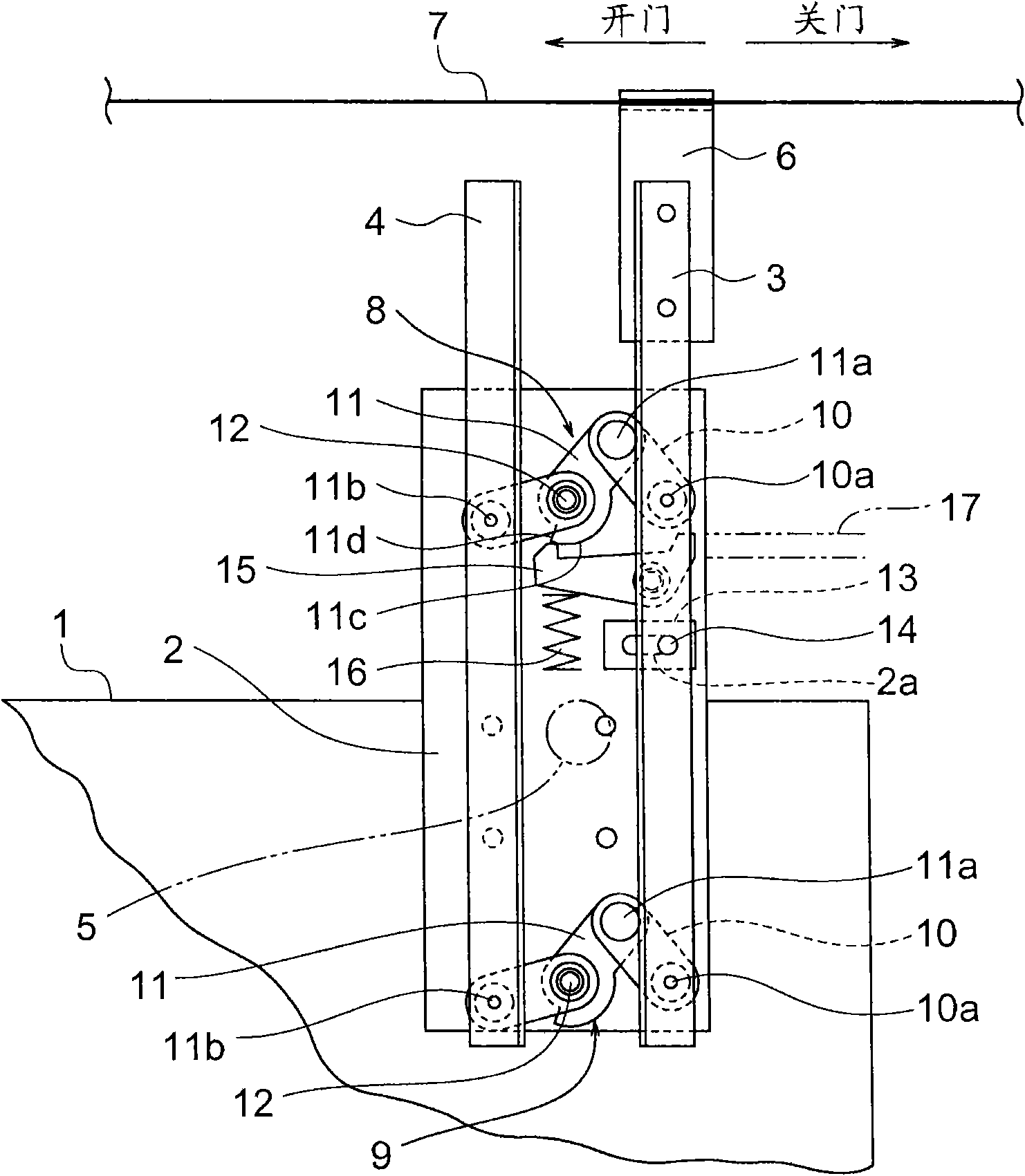
[0016] figure 1 It is a front view of the elevator door engaging device according to Embodiment 1 of the present invention viewed from the hall side. In the drawing, a base plate 2 is fixed to an upper portion of a car door 1 . A first engaging member (driving-side engaging fin) 3 and a second engaging member (driven-side engaging fin) 4 are provided on the base plate 2 . The longitudinal directions of the first and second engaging members 3 and 4 are parallel to the vertical direction.

[0017] In addition, the first and second engaging members 3 and 4 are in the opening and closing direction of the car door 1 ( figure 1 in the left-right direction) and are spaced apart from each other. The spacing between the first and second engaging parts 3, 4 can vary. When the car moves into the door area, the engaging roller 5 provided on the landing door (not shown) as the engaging portion on the landing door side is located between the first and second engaging members 3 , 4 . In...

Embodiment approach 2

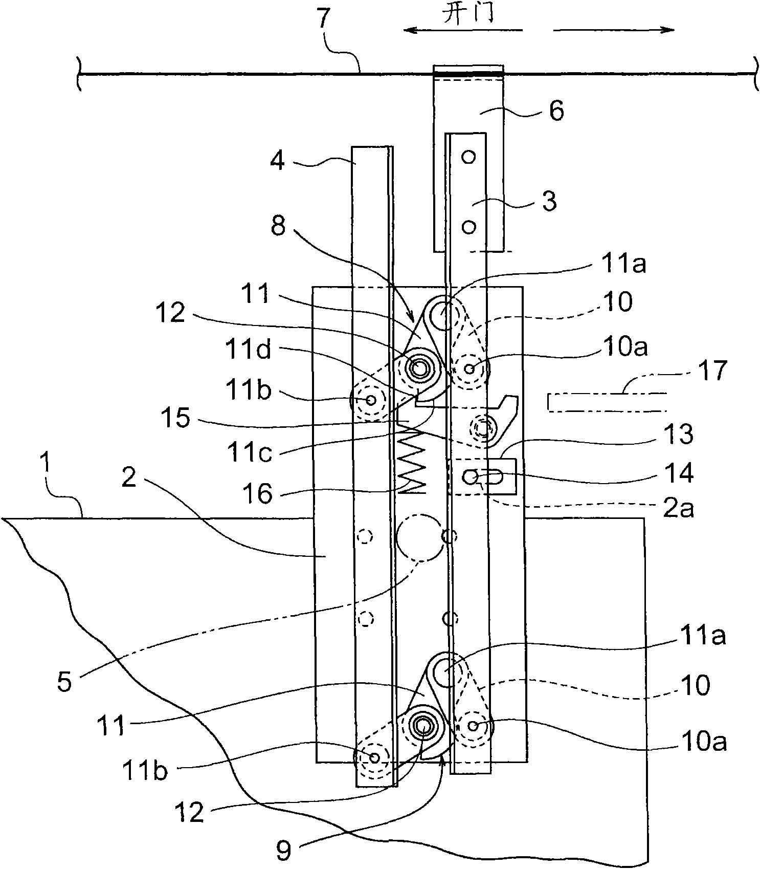
[0043] Next, image 3 It is a front view of the elevator door engaging device according to Embodiment 2 of the present invention viewed from the hall side. In the drawing, a guide mechanism 18 is provided between the base plate 2 and the first engaging member 3 , and the guide mechanism 18 limits the movement of the first engaging member 3 to the horizontal direction. The guide mechanism 18 has: a guide plate 19 provided on the base plate 2 ; and a guide roller 20 provided on the first engaging member 3 and rolling along the upper surface of the guide plate 19 . The upper surface of the guide plate 19 is provided parallel to the opening and closing direction of the car door 1 . Other structures are the same as those in Embodiment 1.

[0044] When the self-weight of the second engaging member 4 is sufficiently light relative to the rigidity of the driving belt 7, the driving belt 7 hardly bends due to the self-weight of the second engaging member 4, and the possibility of rai...

Embodiment approach 3

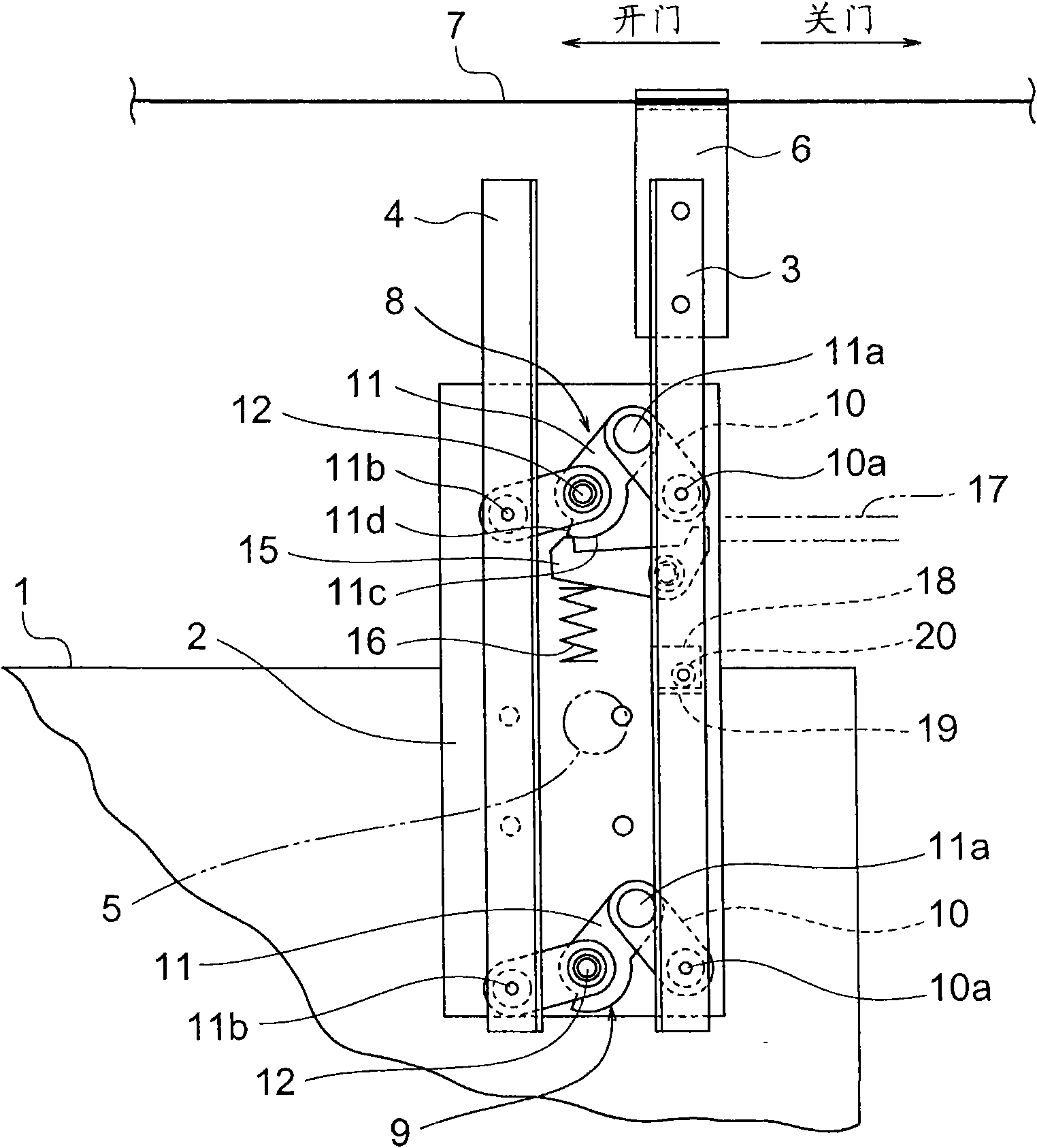
[0047] Next, Figure 4 It is a front view of the door engaging device of an elevator according to Embodiment 3 of the present invention viewed from the hall side. In Embodiment 3, the guide mechanism 13 in Embodiment 1 is omitted. Other structures are the same as those in Embodiment 1.

[0048] When the self-weight of the first engaging member 3 including the joint fitting 6 and the self-weight of the second engaging member 4 are sufficiently light relative to the rigidity of the driving belt 7, the possibility of the position of the first engaging member 3 changing up and down is low Next, it can also be as Figure 4 The guide mechanisms 13, 18 are omitted from the illustration. In this case, the drive belt 7 itself can be used as a guide to move the first engaging member 3 horizontally, thereby enabling simplification and cost reduction of the device.


PUM


Abstract

The invention provides a door engaging device for an elevator, first and second engagement members are provided to a car door through an intermediation of a plurality of interlocking link mechanisms.The interlocking link mechanisms displace the first and second engagement members in an interlocked manner to change a distance between the first and second engagement members. A power transmission body is moved in a direction in which the car door opens and closes by a drive motor for opening and closing the car door. A transmission body connecting portion connected to the power transmission bodyis provided on the first engagement member. The interlocking link mechanisms displace the first engagement member in parallel to the direction in which the car door opens and closes by movement of the power transmission body.

Description

technical field [0001] The invention relates to a door engaging device for synchronously driving the car door and landing door of an elevator. Background technique [0002] In a conventional elevator door engaging device, the first and second runners are linked by a pair of link mechanisms to engage and disengage with the engaging rollers of the landing door. Each link mechanism has an adjustment member rotatably provided on the car door, and a joint member rotatably connected to one end of the adjustment member. The joint part is rotatably connected to the first slider part. The other end of the adjustment member is rotatably connected to the second slider. The adjustment member is connected to a drive belt circulated by a drive motor. And, the adjustment member rotates by the circulation of the drive belt, whereby the first and second sliders are opened and closed (for example, refer to Patent Document 1). [0003] Patent Document 1: Japanese Patent Laid-Open No. 2005-...

Claims


Application Information

Patent Timeline
Patent Type & Authority Applications(China)
IPC IPC(8): B66B13/12
CPCB66B13/12B66B13/16
Inventor 木川弘伊藤直俊小泉喜彦
Owner MITSUBISHI ELECTRIC CORP
Why Eureka
Try Eureka