Switching arrangement

A switchgear, switch shaft technology, applied in the direction of electric switches, transformers, electrical components, etc., can solve the problem of the limited structure planning of switchgear, achieve the effect of reducing parts, low cost, and reducing components

Active Publication Date: 2010-03-24
MASCHFAB REINHAUSEN GEBR SCHEUBECK GMBH & CO KG
View PDF1 Cites 12 Cited by
  • Summary
  • Abstract
  • Description
  • Claims
  • Application Information

AI Technical Summary

Problems solved by technology

[0007] The two functional planes normally required for each phase severely limit the possible structural planning due to the length range of the switchgear

Method used


Image

  • Switching arrangement
  • Switching arrangement
  • Switching arrangement

Examples


Embodiment Construction

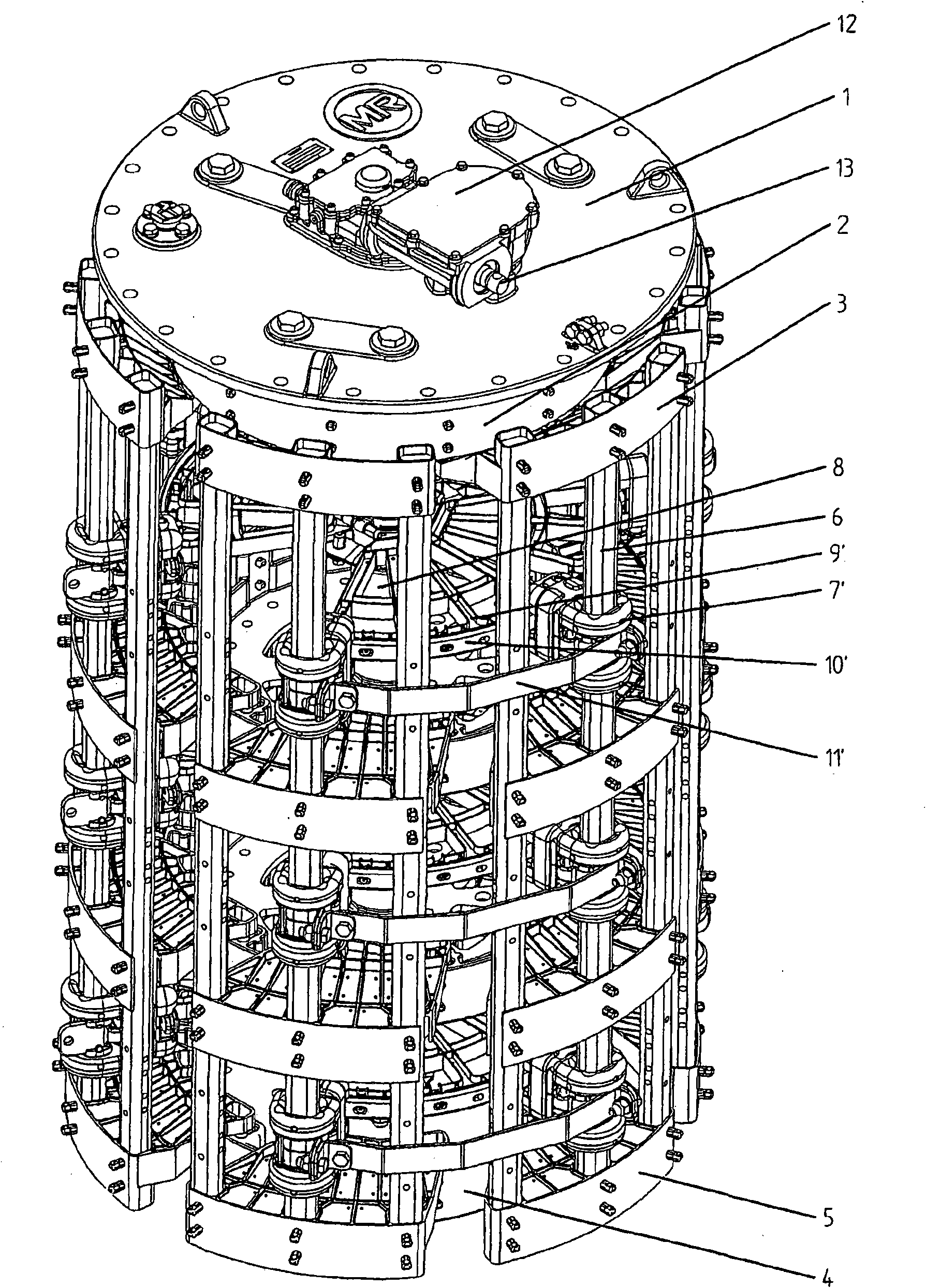
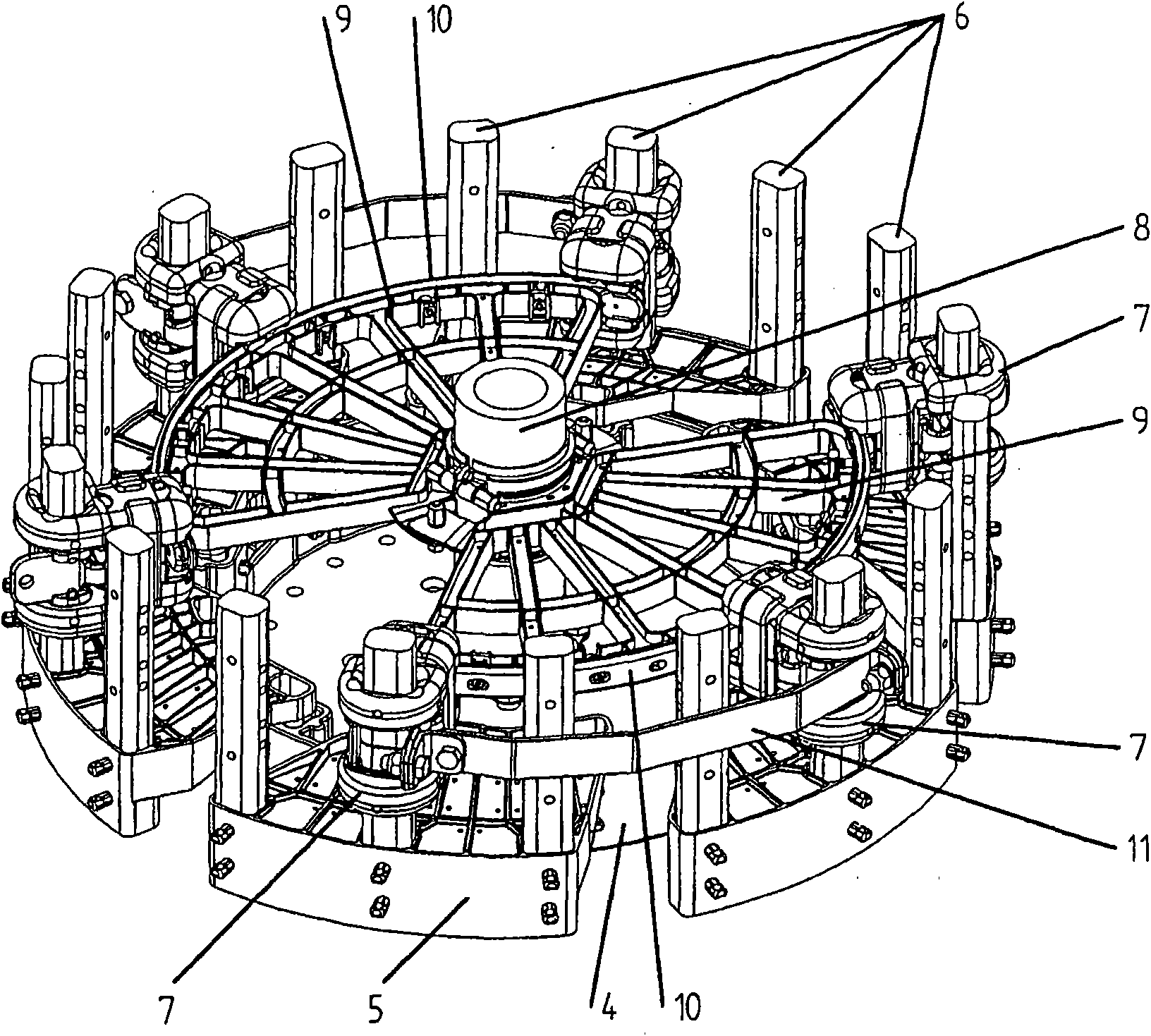
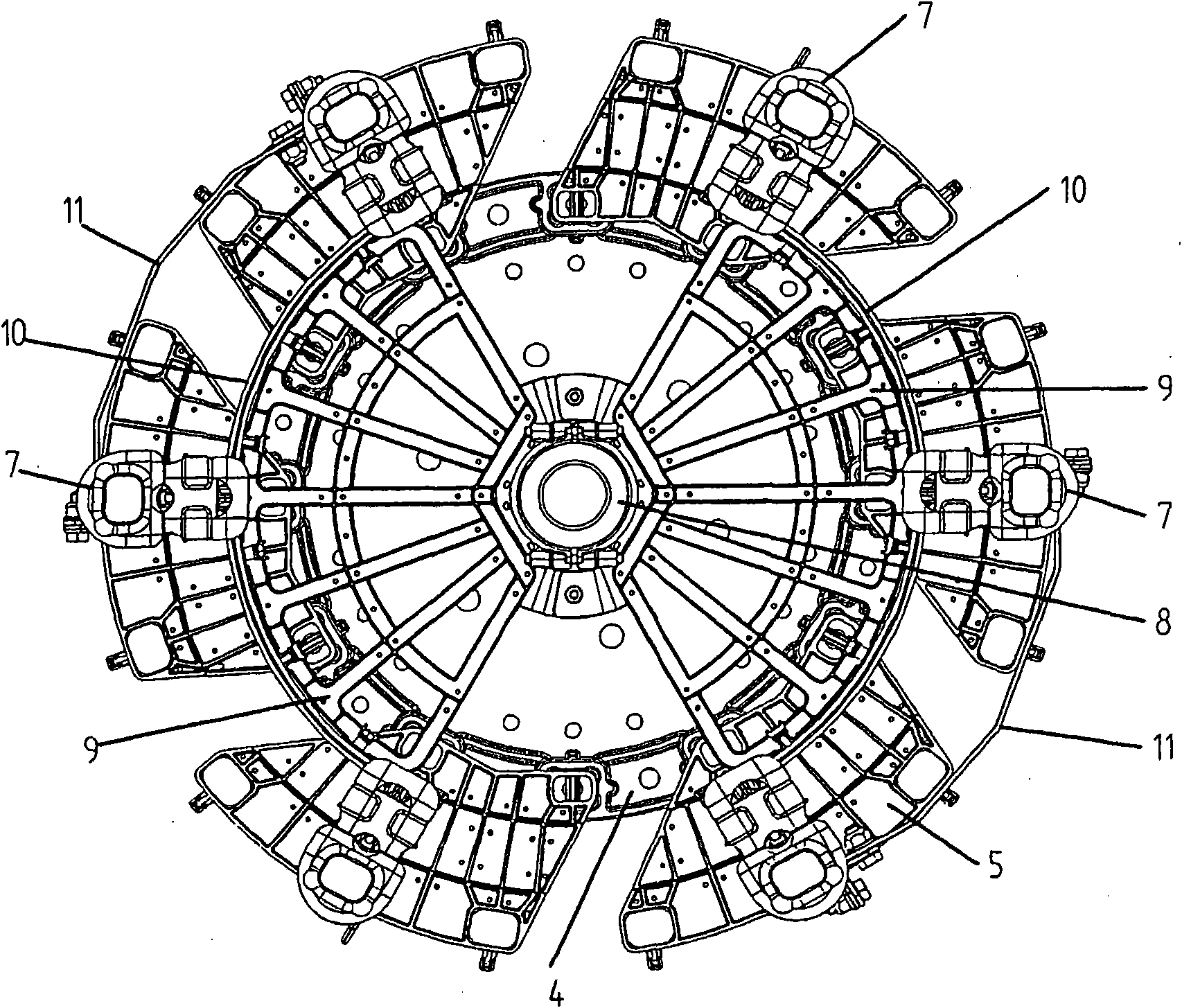
[0024] exist figure 1 As shown in , the switching device has on the upper side a known per se switching head 1 , to which a surrounding upper cage ring 2 is fastened. An upper adapter 3 is again arranged on the cage ring. On the lower end, the lower cage ring 4 and the lower adapter 5 are also fixedly arranged on the cage ring. Between the upper adapter 3 and the lower adapter 5 there are contact rods 6 extending vertically and arranged parallel to each other. In the arrangement shown here, eighteen such contact rods 6 are each fastened arranged at an angle of 20° to one another. On the six contact bars, fixed contacts 7 are respectively fixed in three different horizontal planes, here a plane is set for each phase to be connected, and as the total current increases, the number of planes also increases . The contact rods 6 that are still free are so-called hollow rods, which serve to improve the rigidity of the overall arrangement. exist figure 1 A total of six fixed con...


PUM


Abstract

The invention relates to a switching arrangement having two operating positions for switching a coil during transformer operation, wherein a through current commutates from one current path to anothercurrent path during the switching operation. For this purpose, fixed contacts are arranged on an insulation material frame on multiple horizontal planes about a pivoting selector shaft, said contactshaving upper and lower contact fingers that can be spread apart and can be interconnected as movable switching contacts by means of an electrically conducting terminal.

Description

technical field [0001] The invention relates to a (tap changer) switching device with two operating positions for switching a winding during operation of a transformer, wherein during switching the flow current is switched from one current path to the other. Background technique [0002] By the applicant's company publication "Advanced-Retard-Switch (ARS), Betriebsanleitung BA 274 / 01" (publication note BA 274 / 01de, 0605, date of publication June 2005) under the name "Advanced Retard Switch", abbreviated Such switching devices are known from ARS. The known switching device can be used in different applications in combination with a load step-up switch. It is preferred for pole changing of control voltages in applications with large regulation areas, such as in phase-shifting transformers. Here it fulfills the function of a bidirectional commutator (Doppelwender). [0003] In this known arrangement, two horizontal planes are usually provided for each phase to be switched. ...

Claims


Application Information

Patent Timeline
Patent Type & Authority Applications(China)
IPC IPC(8): H01H1/36H01H9/00H01H19/12
CPCH01H19/12H01H1/36H01H9/0016H01F29/02H01H9/00
Inventor C·哈默T·胡伯尔A·施米德鲍尔
Owner MASCHFAB REINHAUSEN GEBR SCHEUBECK GMBH & CO KG
Why Eureka
Try Eureka