Water drainage structure for electric connection box

一种电连接箱、结构体的技术,应用在电路或流体管路、电气元件、电气设备外壳/柜子/抽屉等方向,能够解决不能充分防止浸水、模具结构复杂、绝缘不良等问题,达到结构简单、缓和压力、防止浸水的效果

Active Publication Date: 2010-03-24
FURUKAWA ELECTRIC CO LTD +1
View PDF1 Cites 9 Cited by
  • Summary
  • Abstract
  • Description
  • Claims
  • Application Information

AI Technical Summary

Problems solved by technology

As a result, water will adhere to the terminal part T of the assembled wire harness W, etc., resulting in poor insulation or corrosion, and there will be a problem that water immersion cannot be sufficiently prevented.
[0019] In addition, there is another problem that it is necessary to make the drainage hole 51 have a crank-shaped structure in order to block the intruded water, thus causing the structure of the mold to be complicated and difficult to manufacture.
[0020] Conventional example 2 has the following problem: In order to arrange the reflection member, it is necessary to newly form a stepped portion on the discharge port, which makes the structure more complicated
[0021] Conventional Example 3 has the following problems: In order to movably support the waterproof cover, it is necessary to form a drainage hole wall, which makes the structure complicated

Method used


Image

  • Water drainage structure for electric connection box
  • Water drainage structure for electric connection box
  • Water drainage structure for electric connection box

Examples


Embodiment Construction

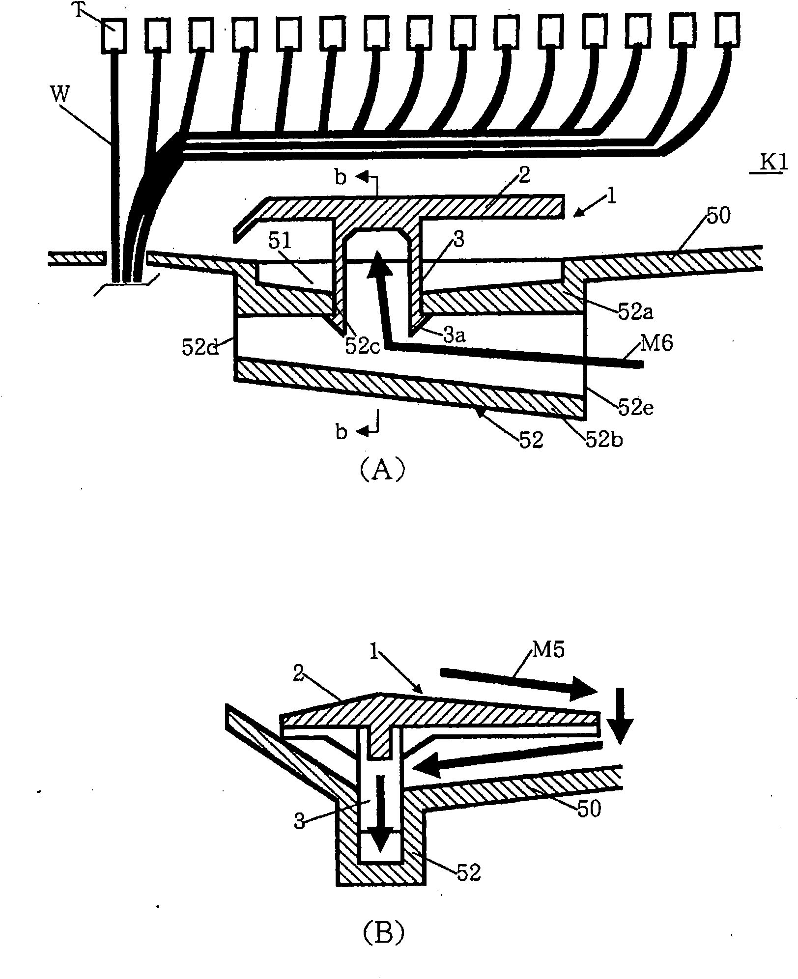
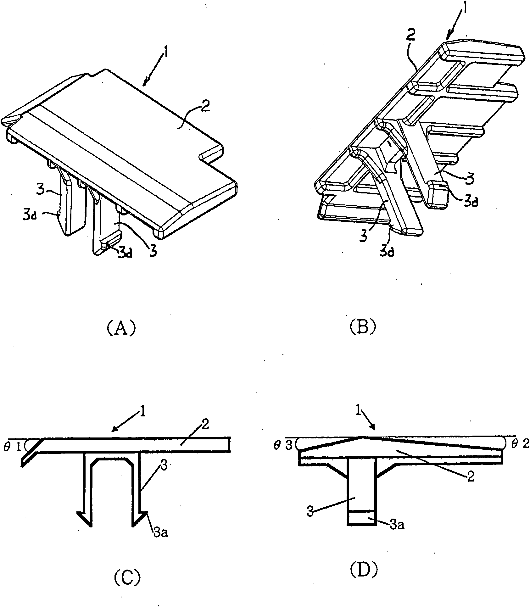
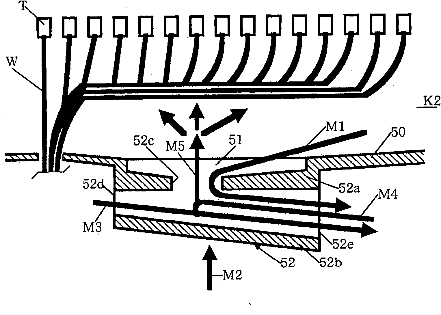
[0044] Hereinafter, embodiments of the present invention will be described with reference to the drawings. figure 1 (A) is a cross-sectional view showing the drainage structure of the electrical junction box in an embodiment of the present invention, (B) is a cross-sectional view of line b-b of (A), figure 2 (A) is a perspective view showing the waterproof cover seen from above, (B) is a perspective view showing the waterproof cover seen from below, (C) is a front view showing the waterproof cover, and (D) is a side view showing the waterproof cover view.

[0045] Such as figure 1 As shown, the feature of the drainage structure K1 of the electrical connection box in the embodiment of the present invention is: the waterproof cover 1 is installed on image 3 On the drain 52 shown.

[0046] The waterproof cover 1 includes a substantially flat cover portion 2 and a pair of hook portions 3 provided on the lower portion of the cover portion 2 .

[0047] The claws 3a are formed...


PUM


Abstract

The object of the inventon is to provide a water drainage structure for an electric connection box, which can sufficiently prevent entry of water into the box and which has a simple structure. In thewater drainage structure (K1), a pair of engagement legs (3) of a waterproof lid (1) is engaged with the peripheral edge of a communication opening (52c) of a water drainage section (52) and a lid (2)is installed so as to cover the upper part of a water drain hole (51). The construction enables that water attempting to enter the inside of the electric connection box via the communication opening(52c) of the water drainage section (52) and via the water drain hole (51) to be blocked by the lid (2) of the waterproof lid (1). Further, the construction prevents blow up of water to the inside ofthe electric connection box and also prevents adhesion of water to terminals (T) and other portions of electric wires (W) of wire harnesses arranged in the electric connection box. As a result, the entry of water into the box is sufficiently prevented. Because the waterproof lid (1) is a separate body from a lower case or a lower cover, the waterproof lid (1) can be applied to a conventional structure and has a simple structure. Thus, the electric connection box has an increased degree ofdesign freedom.

Description

technical field [0001] The present invention relates to a drainage structure of an electrical junction box mounted on an automobile, etc., and more particularly to a drainage structure of an electrical junction box that prevents water from entering from the outside while draining water inside the electrical junction box. Background technique [0002] In vehicles such as automobiles, electrical connection boxes such as contact boxes, fuse boxes, and relay boxes are generally used to house components for wire herness connection and electronic components such as fuses, relays, and electronic control units. [0003] The electrical connection box is mostly arranged on the lower side of the engine box and the car body. In the case of heavy rainfall, washing with high-pressure water, and actual vehicle tests such as jumping into a pool, water often enters the inside of the electrical connection box. In addition, dew condensation sometimes occurs in the electrical connection box, an...

Claims


Application Information

Patent Timeline
Patent Type & Authority Applications(China)
IPC IPC(8): H02G3/16B60R16/02
CPCH02G3/088H05K5/0213B60R16/0238H05K7/026H05K5/0214H05K5/0212
Inventor 油谷健吾内见文和高濑正己
Owner FURUKAWA ELECTRIC CO LTD
Why Eureka
Try Eureka