Wheel braking mechanism

A brake mechanism and wheel technology, applied in the direction of gear transmission mechanism, brake type, trolley, etc., can solve the problems of high local stress and low contact area

Inactive Publication Date: 2010-03-31
MAMAS & PAPAS HLDG
View PDF3 Cites 5 Cited by
  • Summary
  • Abstract
  • Description
  • Claims
  • Application Information

AI Technical Summary

Problems solved by technology

A further problem encountered with known brakes is that when the pin engages the pin seat, if the wheel rotates while the brake is engaged, the pin

Method used


Image

  • Wheel braking mechanism
  • Wheel braking mechanism
  • Wheel braking mechanism

Examples


Embodiment Construction

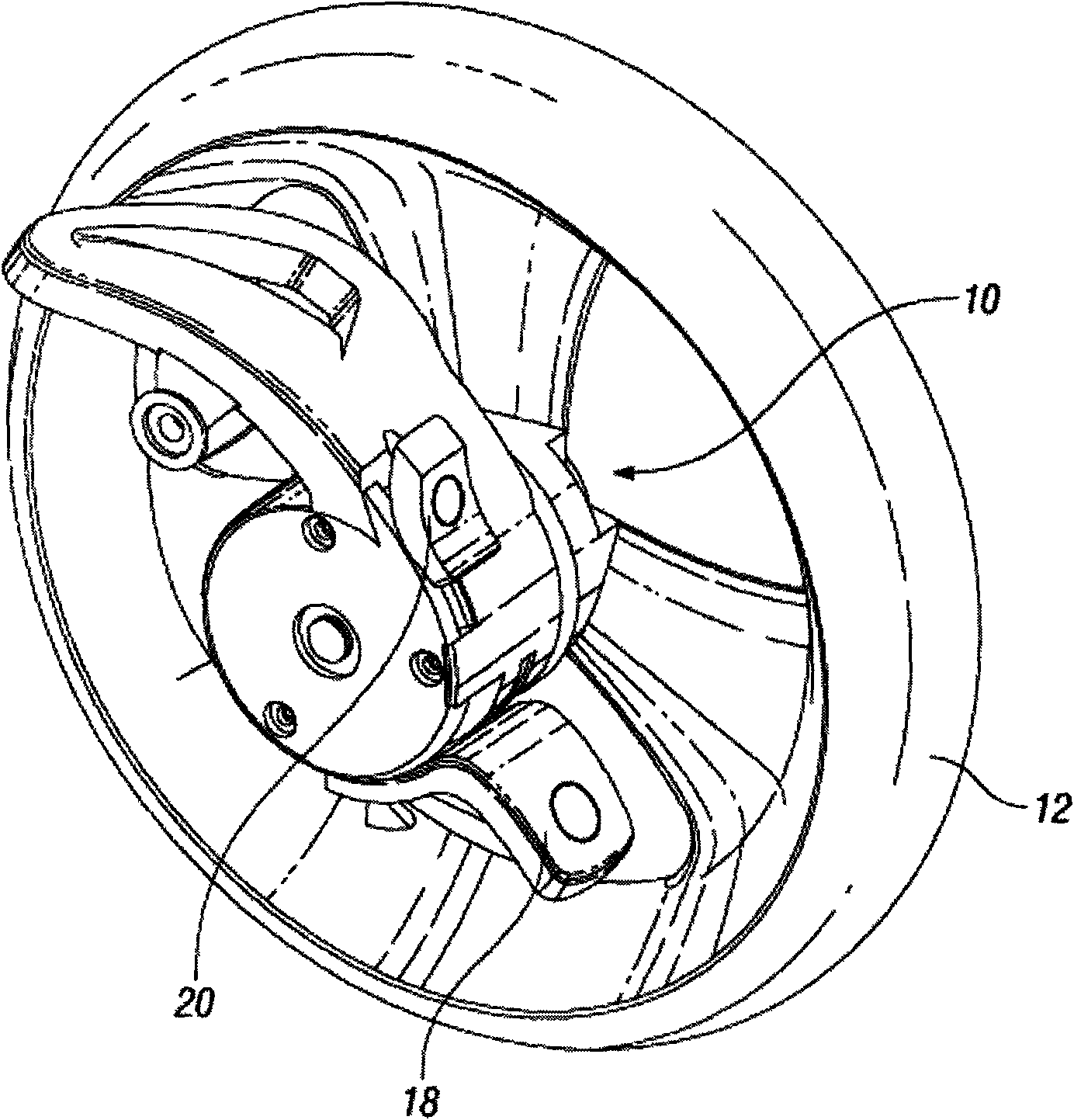
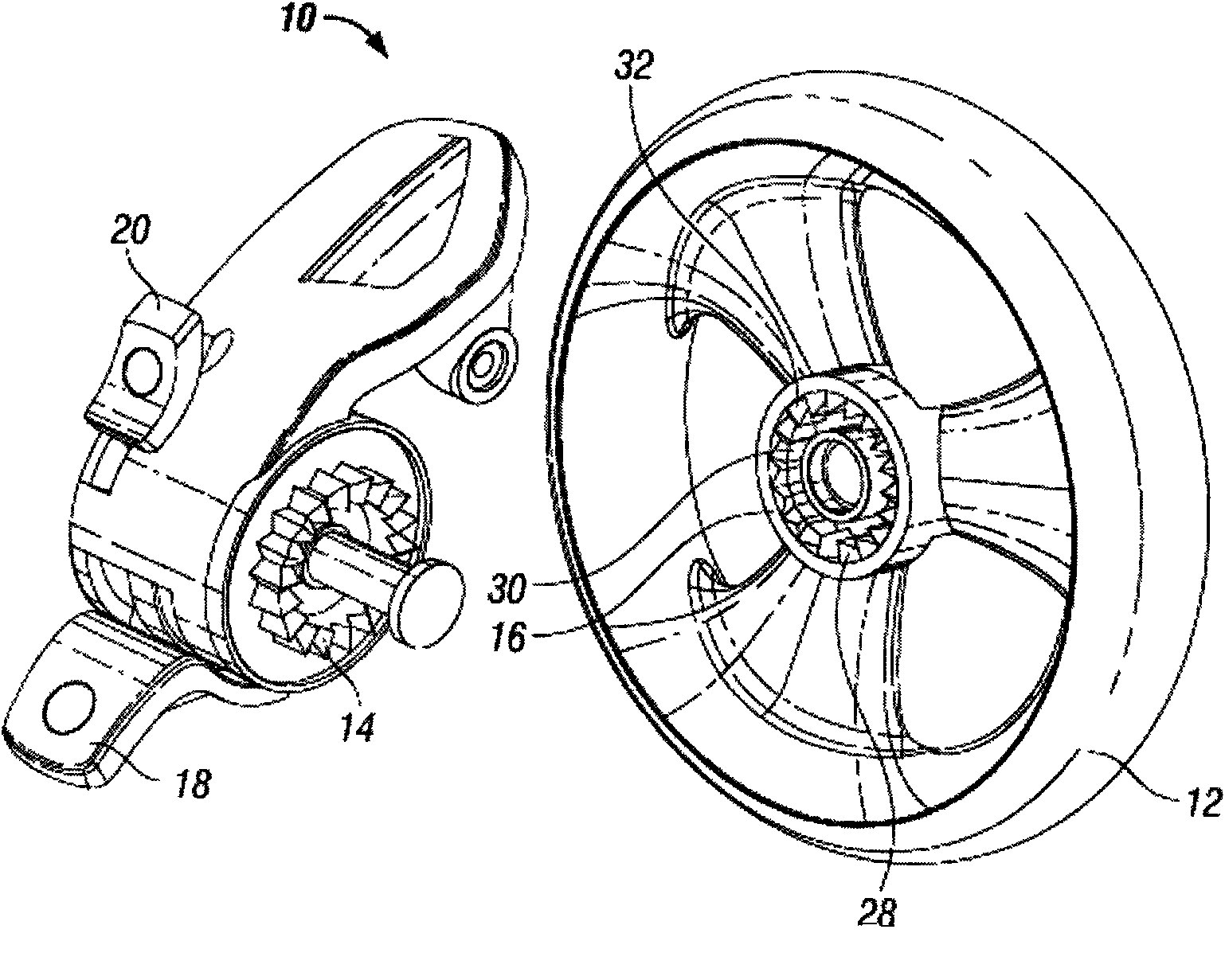
[0038] See figure 1 To 6, it shows the wheel brake mechanism 10 provided on the wheel 12 of the first embodiment of the present invention. The brake mechanism 10 includes a first brake element in the form of a brake shaft 14, a second brake element in the form of a brake drum 16, and a transmission device, including engagement (brake activation) pedal 18 and release (brake release) ) Pedal 20.

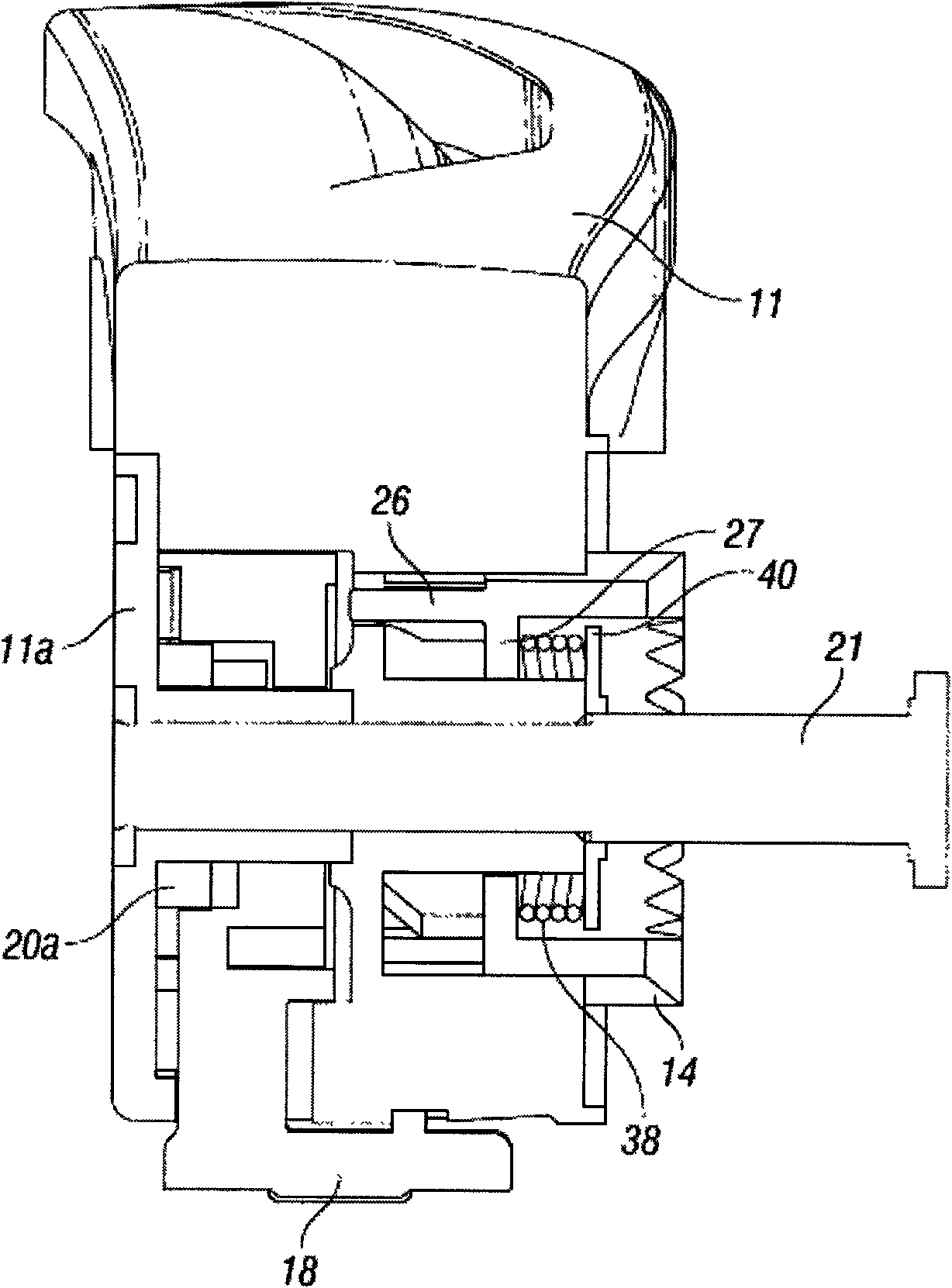
[0039] The brake shaft 14, the start pedal 18 and the release pedal 20 are provided in the brake box 11 and fixed on the center arm 21.

[0040] The brake shaft 14 has a plurality of first splines 22 provided in an adjacent series surrounding the outside of the brake shaft 14. The first splines 22 generally have a triangular cross-section, thereby giving each first spline 22 two engagement surfaces 22a, 22b. The first calibration element 24 is provided on top of each first spline (best see Fig. 6). The calibration elements 24 each have first and second opposing grooved calibration surfac...


PUM

PropertyMeasurementUnit
Inclinationaaaaaaaaaa

Abstract

A wheel braking mechanism (10) comprising a brake shaft (14), a brake drum (16), an engagement pedal (18) and a disengagement pedal (20). The brake shaft (14) has a plurality of first splines provided around the brake shaft (14). A first alignment member is provided at the end of each first spline and has first and second oppositely directed chamfered alignment surface. The brake drum (16) defines a brake socket around which are provided a plurality of second splines (28), which define a plurality of spline recesses (30). A second alignment member is provided at the opposing end of each second spline (28). Movement of the brake shaft (14) towards the brake drum (16) causes the first alignment members to travel down the respective alignment surfaces of the second alignment members, therebyaligning the first splines with the respective adjacent spline recess (30).

Description

Technical field [0001] The present invention relates to a wheel brake mechanism, and particularly but not exclusively, to a wheel brake mechanism for a pushchair. Background technique [0002] The brake mechanism on the wheel of a folding stroller typically includes an axial brake pin, which can be selectively brought in to engage with one of a plurality of pin seats provided on the hub, or a radial brake A drop pin, which can be brought in to mesh with an open gear provided radially on the hub. The problem encountered by these existing brake mechanisms is that when the wheel is loose, the brake pin may not be aligned with one of the multiple pin seats or between the gear teeth, making the engagement of the brake difficult and requiring oscillation. Wheel so that the pin and seat are aligned. Parents have to rotate the wheels to align the pins and seats when they need to brake. A further known problem with braking is that when the pin is engaged with the pin seat, if the wheel...

Claims


Application Information

Patent Timeline
IPC IPC(8): B62B9/08
CPCA61G5/1005A61G5/101F16D2125/36F16D63/006B62B5/0433F16D2121/14B62B5/0457A61G5/1021A61G5/1037B62B9/08
Inventor 尼古拉斯·詹姆斯·迈沃安德鲁·戈登·华莱士
Owner MAMAS & PAPAS HLDG
Why Eureka
Try Eureka