Settlement test method for embankment filling construction

A test method and embankment technology, applied in the directions of roads, roads, measuring devices, etc., can solve the problems of inaccurate measurement, deflection of the settlement pipe, easy to break, etc., and achieve the effect of good application effect, convenient operation and convenient passage.

Inactive Publication Date: 2010-03-31
刘汉龙
View PDF0 Cites 9 Cited by
  • Summary
  • Abstract
  • Description
  • Claims
  • Application Information

AI Technical Summary

Problems solved by technology

[0005] (1) There are generally two types of protective pipes, one is plastic pipes and the other is steel pipes. The protective pipes must protrude from the ground. In this way, in the actual construction process, especially when the embankment itself is not wide, it will bring troubles to the construction vehicles. It is very inconvenient. Construction vehicles must detour when encountering protective pipes protruding from the ground, otherwise it is very easy to break or bend the protective pipes, resulting in inability to measure embankment settlement or inaccurate measurement;
[0006] (2) Since the protective pipe protrudes from the ground, the bulldozer pushes the soil from one side when filling the soil. When the protective pipe is buried with soil, the protective pipe may be deflected, resulting in the deflection of the settlement pipe and causing measurement errors;
[0007] (3) Since the protective pipe protrudes from the ground, in order to protect the protective pipe, the soil within a certain range near the protective pipe cannot be rolled when the filling is rolled, so that this part of the soil cannot be fully compacted, which affects the quality of embankment filling

Method used


Image

  • Settlement test method for embankment filling construction
  • Settlement test method for embankment filling construction
  • Settlement test method for embankment filling construction

Examples


Embodiment Construction

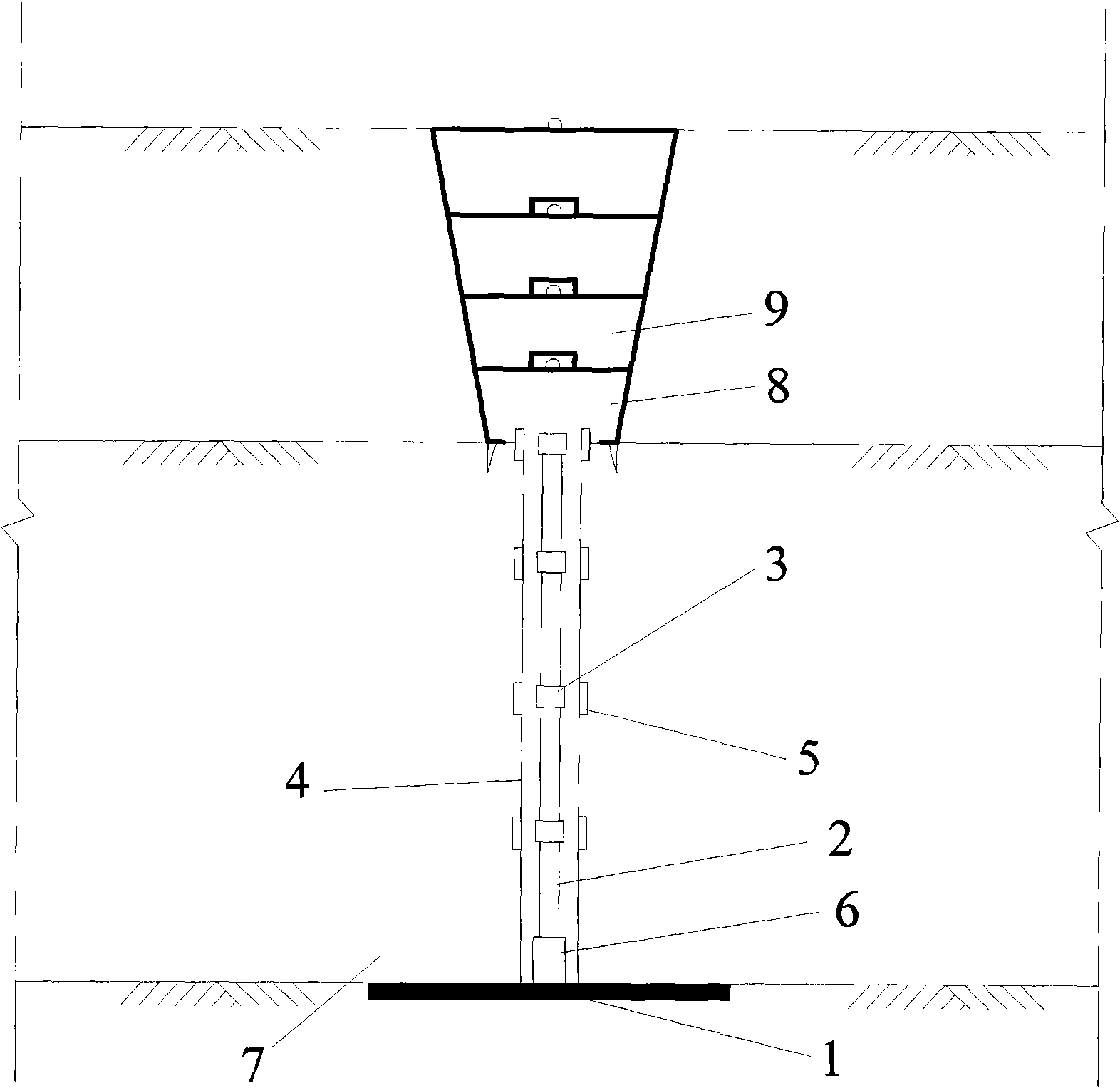
[0028] Such as figure 1 , 2 , 3, and 4 show:

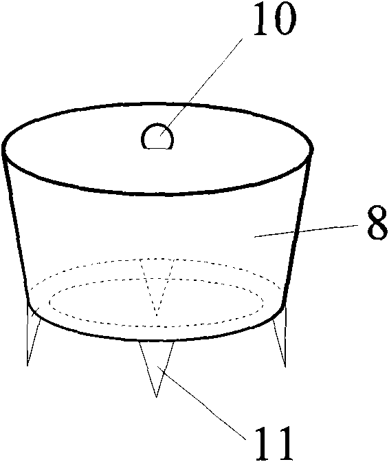
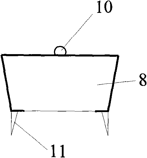
[0029] A settlement test method during embankment filling construction, the monitoring device is composed of a settlement plate 1, a settlement pipe 2, a protective pipe 4, a protective cover 8, and a cushion block 9.

[0030] The settling plate 1 is a square steel plate with a side length of 40cm; the connecting steel pipe 6 is fixed on the settling plate 1, and its height is 10cm; A threaded steel pipe with a diameter of 3 to 5 cm, and the inside of the settlement pipe joint 3 is also threaded, and one section is connected and extended, that is, the settlement pipes 2 of each section are connected to each other through the threaded connection of the settlement pipe joint 3; the protective pipe 4 is a steel pipe or PVC plastic pipe with threads at the upper and lower ends, with a diameter of 5 to 10 cm, connected by a threaded protective pipe joint 5, that is, a section is connected to each other through the protective pipe joi...


PUM


Abstract

The invention relates to a settlement test method for an embankment filling construction. In the invention, a settlement plate is laid flat; a protective cover is placed above the settlement plate; the opening on the lower part of the protective cover faces a connecting steel tube on the settlement plate; the filling height of the embankment is flush with the top part of the protective cover; if the embankment uprises, then a cushion block is placed on the top part of the protective cover repeatedly; a box staff is spanned over any section of a settlement tube after taking away the protectivecover; and the elevation of the settlement plate is measured by using a balance level. The settlement test method for embankment filling construction overcomes the defects that a conventional construction vehicle must make a round when meeting a conduit extending out of a ground surface, and that the embankment settlement cannot be measured or cannot be measured accurately caused by easily breaking or bending the conduit. In construction, the settlement tube is embedded under a marked elevation of filling so as to prevent the construction vehicle from crashing the settlement tube aslant; a deformation space is reserved, the structure is simple, operation is convenient, construction is easy, cost is low and application effect is very good.

Description

technical field [0001] The invention relates to a settlement test method, in particular to a settlement test method during embankment filling construction. Background technique [0002] With the rapid development of highway and high-speed railway construction, more and more high embankments have appeared. The high embankment is a kind of flexible foundation, which is compacted by layered filling and layered rolling on the foundation. Generally, the thickness of each layer of filling is 30cm. The high embankment has a large self-weight, and after filling, it will generate a large additional stress in the foundation soil, which will consolidate the foundation soil and cause settlement. Expressways and high-speed railways have high requirements for embankment settlement, especially post-construction settlement, so long-term observation of settlement is required. [0003] Before the present invention, the commonly used method for observation of composite foundation surface set...

Claims


Application Information

Patent Timeline
Patent Type & Authority Applications(China)
IPC IPC(8): E01C3/00G01C5/00
Inventor 刘汉龙丁选明陈育民周密
Owner 刘汉龙
Why Eureka
Try Eureka