Fluorescent lamps and backlight modules
A fluorescent lamp and fluorescent powder technology, applied in the field of fluorescent lamps, can solve problems such as vibration and electromagnetic interference of fluorescent lamps, and achieve the effect of saving space and avoiding vibration
- Summary
- Abstract
- Description
- Claims
- Application Information
AI Technical Summary
Problems solved by technology
Method used
Image

Examples
Embodiment 1
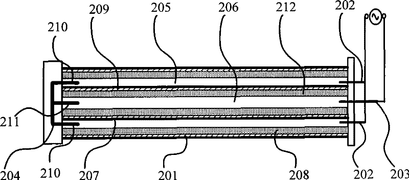
[0023] figure 2 It is a structural schematic diagram of Embodiment 1 of the fluorescent lamp of the present invention. Such as figure 2 As shown, the fluorescent lamp in this embodiment includes an outer lamp tube 201 coated with phosphor powder 208 on the inner wall and an inner lamp tube 209 coated with phosphor powder 212 on the inner wall, and the inner lamp tube 209 is nested inside the outer lamp tube 201 The first end of the outer lamp tube 201 is inserted with a first electrode 202 and a second electrode 203 for a series power supply circuit; a common electrode 204 is arranged inside the second end of the outer lamp tube 201; the first end of the common electrode 204 210 and the first electrode 202 are arranged between the outer lamp tube 201 and the inner lamp tube 209 , and the second end 211 of the common electrode 204 and the second electrode 203 are arranged in the inner lamp tube 209 . The above-mentioned nested double-layer light tube structure is: the area ...
Embodiment 2
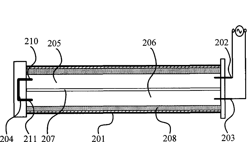
[0026] image 3 It is a structural schematic diagram of Embodiment 2 of the fluorescent lamp of the present invention. Such as image 3 As shown, the fluorescent lamp in this embodiment includes an outer lamp tube 201 whose inner wall is coated with phosphor powder 208, and a first end of the outer lamp tube 201 is inserted with a first electrode 202 and a second electrode 203 for connecting a power supply circuit in series. ; A common electrode 204 is provided inside the second end of the outer lamp tube 201 . The first region 205 and the second region 206 are isolated and formed in the outer lamp tube 201 by an insulating layer 207 . Specifically, the second area 206 is arranged side by side with the first area 205 . The first end 210 and the first electrode 202 of the common electrode 204 are arranged in the first area 205 inside the outer lamp tube 201 , and the second end 211 and the second electrode 203 of the common electrode 204 are arranged in the second area 206 i...
Embodiment 3
[0029] Figure 4 It is a structural schematic diagram of Embodiment 3 of the fluorescent lamp of the present invention. Such as Figure 4 As shown, this embodiment is substantially the same as the fluorescent lamp in the first embodiment above, and the difference is that the inner lamp tube 209 and the outer lamp tube 201 in the first embodiment are filled with inert gas and mercury, and the inner walls of each are coated with In this embodiment, both the inner lamp tube 209 and the outer lamp tube 201 are filled with inert gas and mercury, but only the inner wall of the outer lamp tube 201 is coated with phosphor powder 208 .
[0030] In the fluorescent lamp embodiment of the present invention, the ultraviolet rays generated in the inner lamp tube 209 will directly irradiate the fluorescent powder 208 on the inner wall of the outer lamp tube 201 through the transparent insulating layer 207, so that the brightness of the outer lamp tube 201 increases; The electrons in the tu...
PUM
 Abstract
Description
Claims
Application Information
 - R&D
- Intellectual Property
- Life Sciences
- Materials
- Tech Scout
- Unparalleled Data Quality
- Higher Quality Content
- 60% Fewer Hallucinations
Browse by: Latest US Patents, China's latest patents, Technical Efficacy Thesaurus, Application Domain, Technology Topic, Popular Technical Reports.
© 2025 PatSnap. All rights reserved.Legal|Privacy policy|Modern Slavery Act Transparency Statement|Sitemap|About US| Contact US: help@patsnap.com