Grommet

A component and hole technology, which is applied to vehicle parts, electrical components, multi-purpose hand tools, etc., can solve problems such as difficulty in installation and force transmission

Active Publication Date: 2010-03-31
YAZAKI CORP
View PDF1 Cites 2 Cited by
  • Summary
  • Abstract
  • Description
  • Claims
  • Application Information

AI Technical Summary

Problems solved by technology

For this reason, in the eyelet member 101 of the prior art, it is difficult to transmit the force when pressing when the above-mentioned main body portion 102 is elastically deformed in the diameter-reducing direction, and it is difficult to attach it to the board.

Method used


Image

  • Grommet
  • Grommet
  • Grommet

Examples


Embodiment Construction

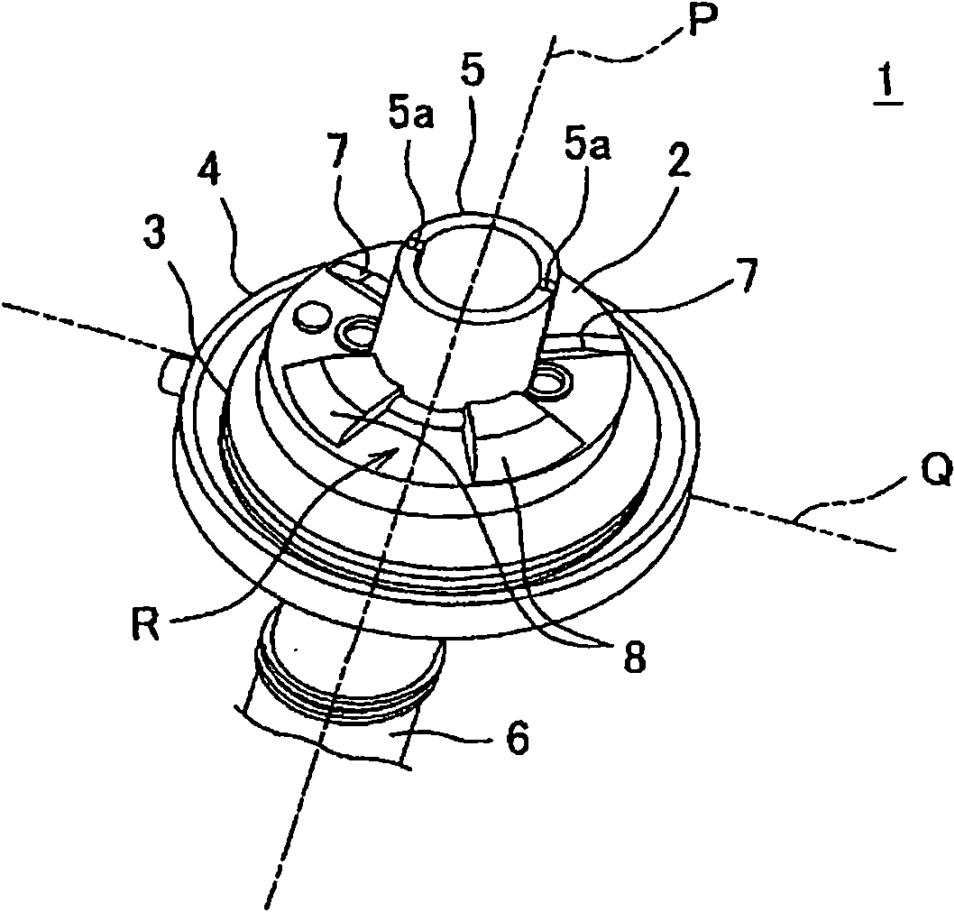
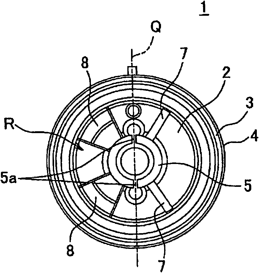
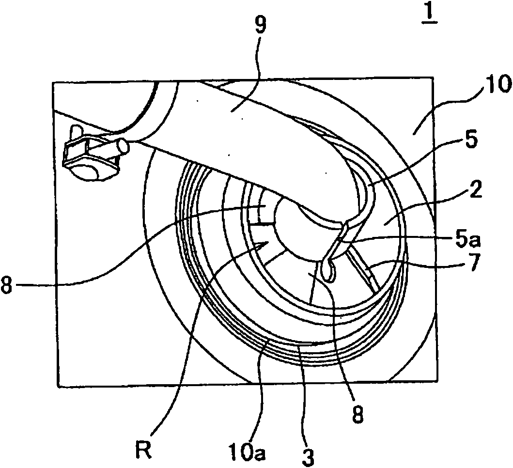
[0032] Below, refer to Figure 1 to Figure 6 An eyelet member according to a first embodiment of the present invention will be described. The eyelet member 1 according to the first embodiment of the present invention is mounted on a vehicle 11 (in Figure 5 In the hole 10a (in the Figure 4 and Figure 5 express). In addition, in this embodiment, the planar shape of the said hole 10a is formed in circular shape.

[0033] The above-mentioned eyelet member 1 is made of freely elastically deformable rubber or the like, and is formed in a cylindrical shape while passing through the wire harness 9 (in the image 3 and Figure 4 express). The eyelet member 1 is watertight with the plate 10 to prevent liquids such as water from infiltrating into the inside from between the plate 10 and to prevent liquids such as water from adhering to the wire harness 9 . Such as Figure 1 to Figure 4 As shown, the eyelet member 1 has a pair of barrel parts 5, 6 and a body part 2 integrally. ...


PUM


Abstract

A grommet that can be easily attached to a panel. The grommet (1) allows a wire harness to pass through it and is attached to a hole (10a) in the panel (10). The grommet (1) includes a tubular body section (2) having formed in its entire periphery an engagement groove (3) engaging the hole (10a). On the outer surface of the body section (2) are arranged a set of two first ribs (8) and a set of twosecond ribs (7) that extend from one end side to the other end side of the body section (2) and are spaced from each other. The first ribs (8) are located on one side of an imaginary plane includinga center axis (P) and a long dashed double-dotted line (Q). The second ribs (7) are arranged on the other side of the imaginary plane. The width of a first rib (8) is greater than the width of a second rib (7).

Description

technical field [0001] The present invention relates to an eyelet member mounted on a panel constituting a vehicle body of an automobile or the like and passing a wire harness inside. Background technique [0002] The wire harness is passed through a hole provided in a panel constituting the body of a motor vehicle, etc., and in order to prevent liquids such as water from adhering to the wire harness, for example, it is used in Figure 9 The eyelet member 101 is shown (for example, refer to Patent Document 1). Figure 9 The eyelet member 101 shown integrally has a cylindrical portion 105, a main body portion 102 connected to the cylindrical portion 105 and whose inner and outer diameters gradually enlarge from one end toward the other end, and a second end connected to the other end of the main body portion 102. The two cylindrical parts 106, the engaging concave part 103 provided on the entire circumference of the main body part 102 and engaged in the hole of the plate, and ...

Claims


Application Information

Patent Timeline
Patent Type & Authority Applications(China)
IPC IPC(8): H01B17/58H02G3/22
CPCB60R16/0222H01B17/583H02G3/22
Inventor 龟上正义
Owner YAZAKI CORP
Why Eureka
Try Eureka