Machine tool design method

A design method and machine tool technology, applied in milling machine equipment, details of milling machine equipment, metal processing equipment, etc., can solve the problem that the machine tool design method is not scientific and reasonable, and achieve the effect of convenient analysis, good versatility, and reasonable means

Inactive Publication Date: 2010-04-07
HANS LASER TECH IND GRP CO LTD +1
View PDF0 Cites 6 Cited by
  • Summary
  • Abstract
  • Description
  • Claims
  • Application Information

AI Technical Summary

Problems solved by technology

[0003] The purpose of the present invention is to provide a kind of machine tool design method, aims at

Method used


Image

  • Machine tool design method
  • Machine tool design method
  • Machine tool design method

Examples


Embodiment Construction

[0020] In order to make the object, technical solution and advantages of the present invention clearer, the present invention will be further described in detail below in conjunction with the accompanying drawings and embodiments. It should be understood that the specific embodiments described here are only used to explain the present invention, not to limit the present invention.

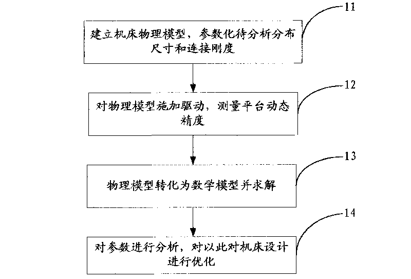
[0021] The machine tool design method provided by the invention is to use dynamic analysis means to determine the performance parameters and combined state of the machine tool's moving functional parts, so that the machine tool dynamic mechanism can run smoothly, and the structural vibration caused by the moving inertia of the driving part of the machine tool can be minimized.

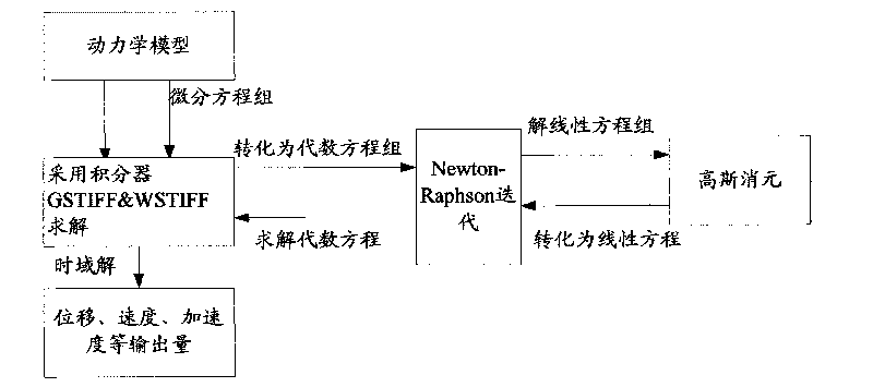
[0022] A preferred embodiment of the present invention is to set up the numerically controlled machine tool dynamics model in the computer, take the dynamic performance performance (machine tool motion trajectory) of the dyn...


PUM


Abstract

The invention provides a machine tool design method, comprising the steps of a) creating a machine tool physical model according to parts processing technology and assembling technology, b) exerting a driving signal to the physical model and measuring the platform dynamic precision, c) transferring the physical model into a mathematical model and solving, d) analyzing the parameters and optimizing the machine tool design. The machine tool design method of the invention directly uses the dynamic property of machine tool as the evaluating object, rigid body dynamics calculation as the manner of analyzing and combined property parameter of motor function element as analyzing and optimizing object, having the advantages of clear target, reasonable method, convenient analysis, etc.

Description

technical field [0001] The invention relates to the field of machine tool design, in particular to an improved machine tool design method. Background technique [0002] High-precision CNC machine tools such as PCB (printed circuit board) board drilling and milling machines are a kind of modern industrial electronic equipment, which involves precision manufacturing technology, automatic control technology, information processing, transmission, etc., and has the characteristics of high speed and high precision. The mechanical body of this kind of high-speed and high-precision machine tool has the following structural characteristics: 1. Accurate transmission and positioning; 2. Small inertia, high rigidity, and small vibration. In the traditional design, the design of this kind of machine tool emphasizes the design, selection, and verification of the size of the parts, and only pays attention to the design of the structural space position. Whether the rest of the performance r...

Claims


Application Information

Patent Timeline
IPC IPC(8): B23B41/02B23C3/00
Inventor 高云峰肖俊君宋福民雷群崔彦洲
Owner HANS LASER TECH IND GRP CO LTD
Why Eureka
Try Eureka