
Two-coin-feed mechanism

A coin and card card technology, which is applied in the direction of coin inlet device, coin accepting device, coin or valuable banknotes, etc., can solve the problem of insufficient function of anti card coin and only one coin can be inserted, so as to achieve the convenience of passengers, The effect of improving efficiency and preventing coin jams

Active Publication Date: 2011-01-19
NANJING CBPM GREAT WALL FINANCIAL EQUIP
View PDF0 Cites 0 Cited by
  • Summary
  • Abstract
  • Description
  • Claims
  • Application Information

AI Technical Summary

Problems solved by technology

[0004] The first technical problem to be solved by the present invention is to overcome the problem that the existing intelligent coin-checking coin machine can only throw one coin at a time, and provide a double-coin throwing mechanism to improve the efficiency of coin checking and coin checking
[0005] The further technical problem to be solved by the present invention is the problem that the anti-stuck coin function of the existing intelligent coin-checking machine is not perfect enough. On the basis of double coin throwing at one time, the coin-stuck phenomenon can be reliably eliminated to further improve the operation of the bus efficiency

Method used


Image

  • Two-coin-feed mechanism
  • Two-coin-feed mechanism
  • Two-coin-feed mechanism

Examples


Embodiment 1

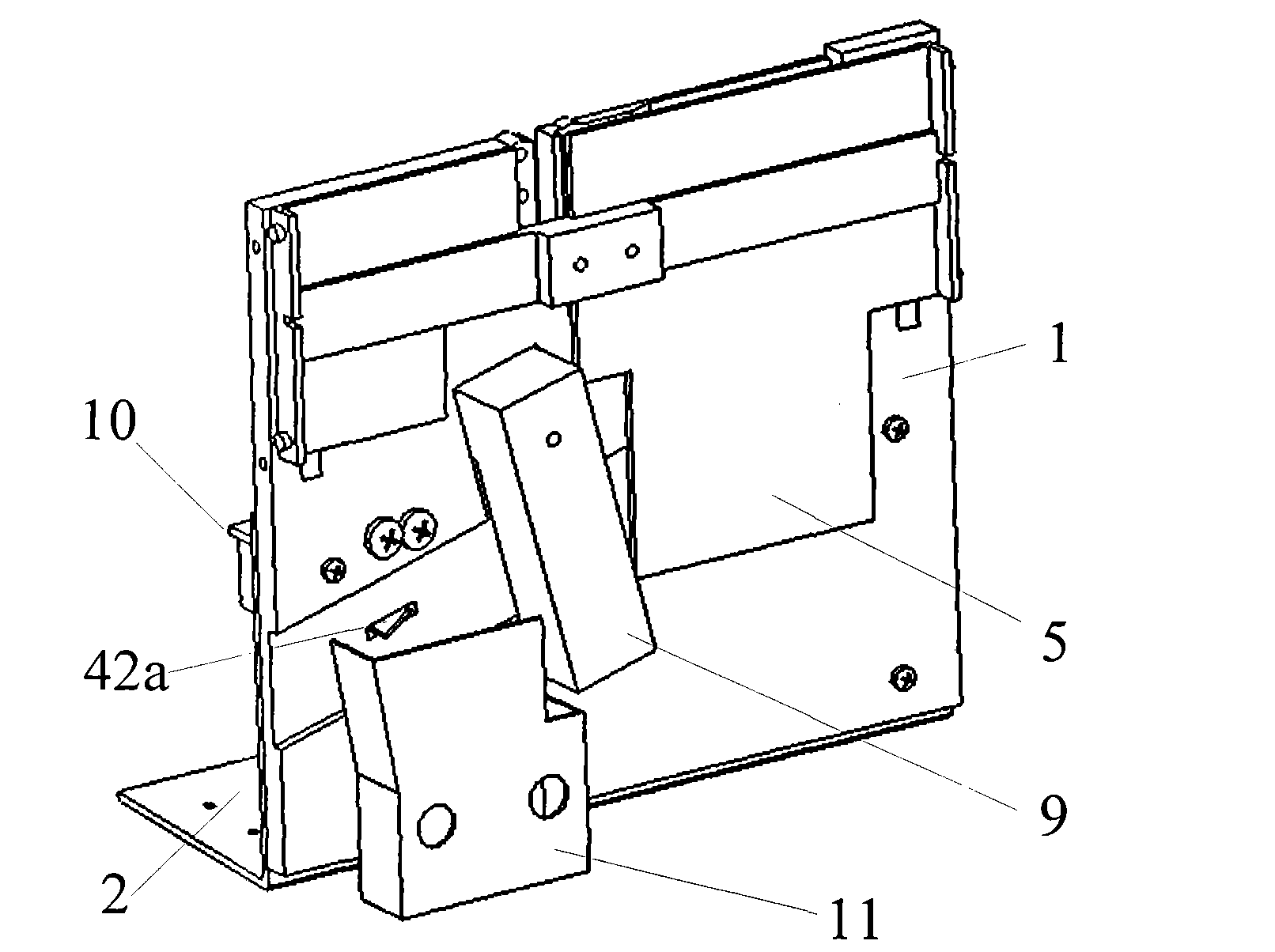
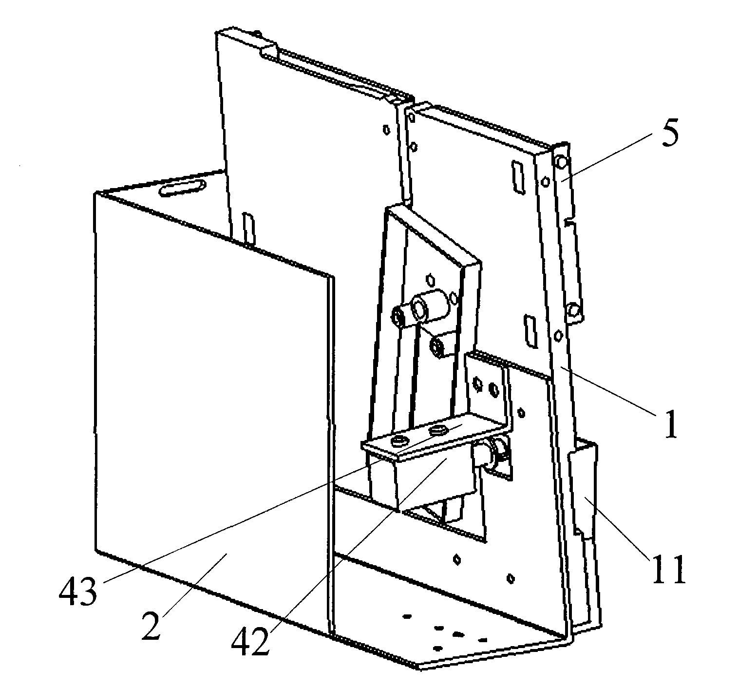
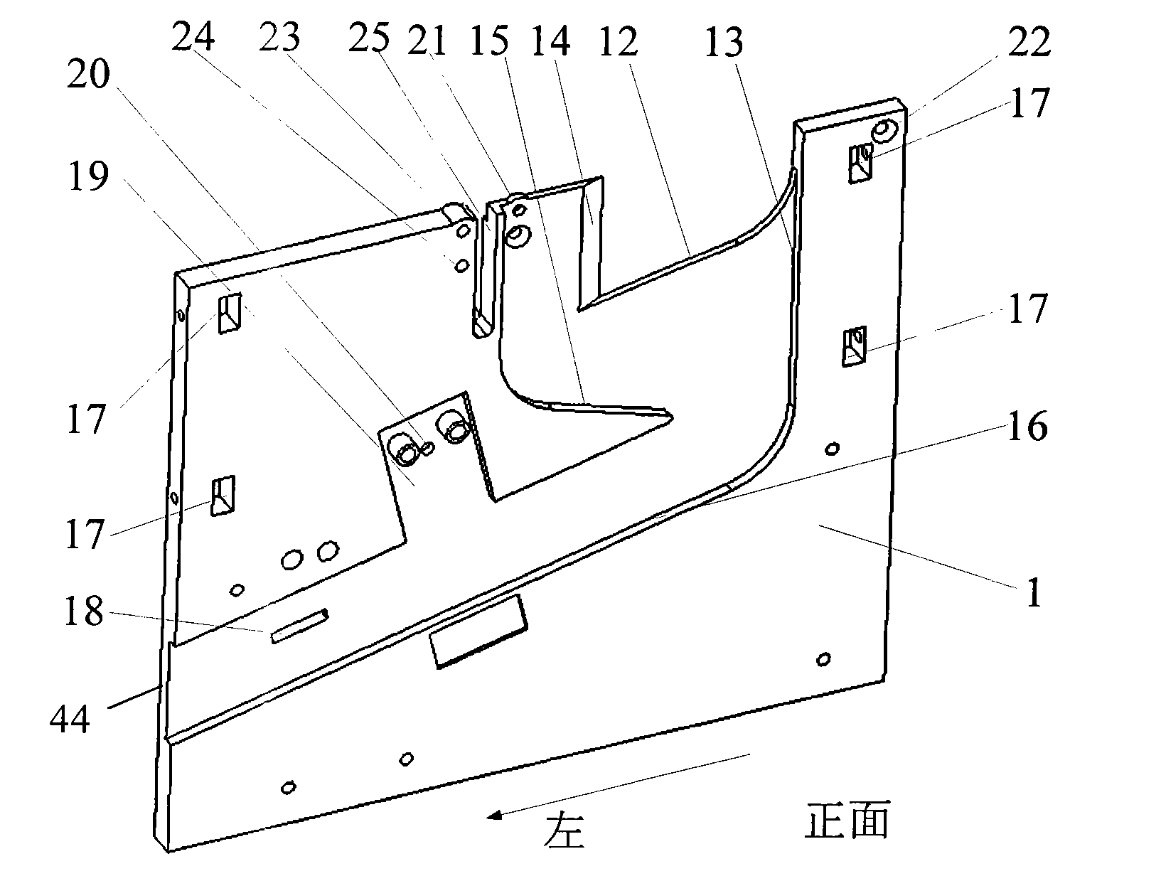
[0029] see Figure 1 to Figure 4 , This embodiment includes a main coin retaining plate 1, a bracket 2, an auxiliary coin retaining plate 5, a sensor 9, an electromagnet assembly 10, and a coin collecting frame 11. The main coin baffle 1 is fixedly connected on the support 2 and slightly inclined backward. The main coin retaining plate 1 is distributed with a first-level slideway 12, a side wall 13, a wedge-shaped slope 14, a second-level slideway 15, a third-level slideway 16, an electromagnet tongue groove 18, a sensor installation groove 19, a sensor installation hole 20, Circuit board mounting slot 27 .

[0030] One-level slideway 12, wedge-shaped slope 14, secondary slideway 15, and third-level slideway 16 are distributed on the main coin retaining plate 1 from top to bottom and from inside to outside, and three slideways are all arranged obliquely. The upper end of the first-level slideway 12 and the side wall 13 transitions are arc-shaped, and the lower end links to e...

Embodiment 2

[0037] see Figure 3 to Figure 7 , Embodiment 2 is based on Embodiment 1 by adding the first cam track assembly 3 , the second cam track assembly 4 and the cam plate 6 .

[0038] The main coin retaining plate 1 is distributed with a first-level slideway 12, a side wall 13, a wedge-shaped slope 14, a second-level slideway 15, a third-level slideway 16, an electromagnet tongue groove 18, a sensor installation groove 19, and a sensor installation hole 20. 1. In addition to the circuit board mounting groove 27, it also includes 4 square holes 17 distributed on the left and right sides of the main coin retaining plate 1. Square nuts are placed inside the first square hole 17, and the first cam guide rail assembly 3 and the second cam guide rail assembly 4 are connected with the main coin retaining plate 1 by screws.

[0039] like Figure 7As shown, the first cam guide rail assembly 3 includes a cam guide rail 28 , a pin shaft 29 , a compression spring 30 , and a compression sprin...

Embodiment 3

[0044] In this embodiment, on the basis of Embodiment 2, a coin ejection assembly 7 and a coin channel assembly 8 are further added. Correspondingly, the main coin retaining plate 1 is distributed with a primary slideway 12, a side wall 13, and a wedge-shaped slope. 14. Secondary slideway 15, third-stage slideway 16, 4 square holes 17, electromagnet outlet tongue groove 18, sensor installation groove 19, sensor installation hole 20, circuit board installation groove 27, also located in the left square hinge Seat mounting hole 21, right square hinge seat mounting hole 22, mounting hole 23 on the boss hinge seat, mounting hole 24 under the boss hinge seat, shift fork groove 25, coin door mounting groove 26. The left square hinge seat installation hole 21 is located in the upper middle of the main coin retainer 1, the left side of the wedge-shaped slope 14, the right square hinge seat installation hole 22 is located at the upper right corner of the main coin retainer 1, the right ...


PUM


Abstract

A two-coin-feed mechanism comprises a frame, a main coin-blocking plate, an auxiliary coin-blocking plate, a sensor and a coin-collecting frame, wherein the main coin-blocking plate is arranged on the frame and provided with a primary slideway, a wedge slope, a secondary slideway and a tertiary slideway, the three slideways are arranged slantly; the transition position between the top end of the primary slideway and the inner sidewall of the main coin-blocking plate is of circular arc form, the bottom end is connected with the wedge slope, the top end of the secondary slideway is arc, the bottom end is floating, the distance between the bottom end and the inner sidewall is more that the diameter of a Yuan coin, the transition position between the top end of the tertiary slideway and the inner sidewall is arc; the auxiliary coin-blocking plate is arranged on the outside of the main coin-blocking plate, an opening formed between the two coin-blocking plates is the coin inlet; the sensoris arranged on the main coin-blocking plate and below the tertiary slideway; and the coin-collecting frame is arranged on the frame and below the tertiary slideway of the main coin-blocking plate. The two-coin-feed mechanism of the invention breaks this limitation of the traditional bus slot machine with cash-detecting function that users can only feed one coin once in the machine and realizes the function that two coins can be fed in the two-coin-feed mechanism and the coin can be detected separately.

Description

technical field [0001] The invention relates to a mechanism capable of inserting double coins, in particular to a mechanism capable of inserting two coins at one time for passengers on a bus. Background technique [0002] The intelligent coin-checking coin machine commonly used on the bus generally can only insert one coin at a time at present. The ticket is usually more than one yuan, which means that passengers have to wait at the slot machine for two, three or even more times of speculation, so that not only the efficiency of coin checking is low, but also once the number of passengers is large, there will be a backlog of passengers Waiting for the coin to be inserted at the front of the bus is not conducive to the exercise of the bus and the boarding and unloading of passengers. Moreover, the anti-coin function of smart coin machines on many buses is not perfect enough, and some do not have the anti-coin function. Once a coin occurs, it will bring great trouble to the o...

Claims


Application Information

Patent Timeline
Patent Type & Authority Patents(China)
IPC IPC(8): G07D11/00G07F1/04G07F9/00
Inventor 张武军梁庆华黄翔罗磊魏家严莫锦秋林传美
Owner NANJING CBPM GREAT WALL FINANCIAL EQUIP
Learn More