Door locking switch and clothing processing apparatus using same
A technology of clothes processing device and locking device, which is applied to the control device of washing machine, washing device, application, etc., can solve the problems of safety accidents, difficulty in opening doors, etc., and achieve the effect of preventing safety accidents
- Summary
- Abstract
- Description
- Claims
- Application Information
AI Technical Summary
Problems solved by technology
Method used
Image

Examples
Embodiment Construction
[0025] Hereinafter, embodiments of the door lock switch and the laundry processing apparatus using the door lock switch in the present invention will be described in detail with reference to the accompanying drawings.
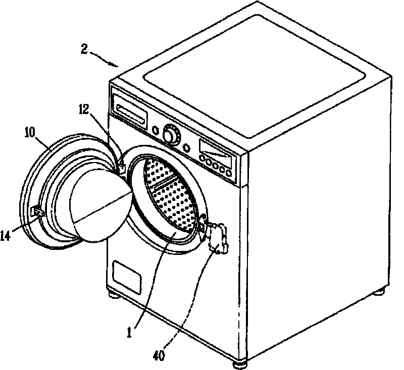
[0026] refer to figure 1 , which illustrates a washing machine using an embodiment of the door lock switch of the present invention. However, the above-mentioned embodiment is not limited to the washing machine, and it can also be applied to any clothes processing device having a door, such as a clothes dryer.
[0027] figure 1 The washing machine shown in the middle figure includes a housing or body 2 formed with a clothes inlet 1, a washing tub is arranged inside the body 2, and a drum rotatably mounted on the washing tub. After the laundry is put in the drum, the drum is rotated, and processes such as washing or drying are performed.
[0028] In addition, the door 10 for opening and closing the above-mentioned clothes delivery port 1 will be fixed on the ...
PUM
 Abstract
Description
Claims
Application Information
PatSnap Eureka turns technology decisions into work you can execute. Powered by our Innovation Knowledge Graph, it runs expert workflows across engineering, life sciences, materials and intellectual property. Get your review-ready output in minutes.


