Connection structure between steering wheel and direction controlling device

A technology of direction control and connection structure, applied in the direction of mechanical steering gear, etc., can solve the problems of inability to fold parts, high manufacturing cost, complex structure, etc., and achieve the effect of simple structure, low production cost and reduced volume

Inactive Publication Date: 2010-04-21
董振丰 +2
View PDF0 Cites 4 Cited by
  • Summary
  • Abstract
  • Description
  • Claims
  • Application Information

AI Technical Summary

Problems solved by technology

The existing connection structure between the steering wheel and the direction control device is a mechanical hard connection. This kind of structure is relatively complicated, the manufacturing cost is also high, and the parts cannot be folded

Method used


Image

  • Connection structure between steering wheel and direction controlling device
  • Connection structure between steering wheel and direction controlling device
  • Connection structure between steering wheel and direction controlling device

Examples


Embodiment 1

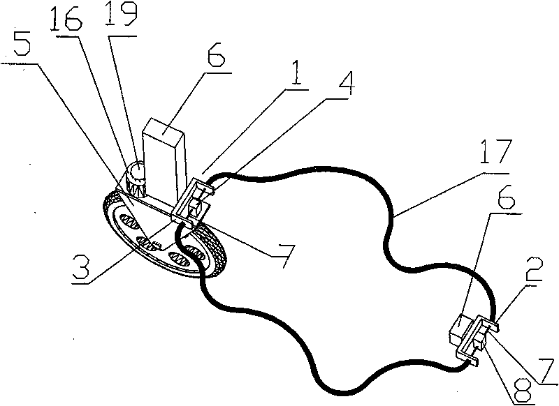
[0019] Embodiment 1: A connection structure between a direction wheel and a direction control device, which includes a direction wheel force receiving device 1 and a direction control clamping plate 2, the direction control clamping plate 2 is fixed on the vehicle main body 6, and the direction wheel The force-bearing device 1 includes a force-bearing block frame 3 and a force-bearing block 4, the force-bearing block 4 is located in the force-bearing block frame 3, the force-bearing block 4 is fixedly arranged on the direction wheel frame 5, and the force-bearing block is clamped The bit frame 3 is fixed on the vehicle main body 6, the axle sleeve 16 on the steering wheel is fixed on the vehicle main body 6, and the steel cable 7 passes through the direction control clamping plate 2 and the force block clamping frame 3 respectively, and the steel cable 7 guides the direction The control device 8 and the stressed block 4 are connected in series to form a loop, and the steel cabl...

Embodiment 2

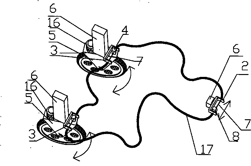
[0020] Embodiment 2: a connection structure between a direction wheel and a direction control device, which includes two direction wheel force-bearing devices 1 and a direction control clamping plate 2, the direction control clamping plate 2 is fixed on the vehicle main body 6, and the direction The wheel stress device 1 comprises a force block frame 3 and a force block 4, the force block 4 is located in the force block frame 3, the force block 4 is fixedly arranged on the direction wheel frame 5, and the force block The locking frame 3 is fixed on the vehicle main body 6, the axle sleeve 16 on the steering wheel is fixed on the vehicle main body 6, and the steel cables 7 pass through the direction control locking plate 2 and the force block locking frame 3 respectively, and the steel cables 7 will The direction control device 8 is connected in series with the two force-bearing blocks 4 to form a loop, and the steel cable 7 between the direction control clamping plate 2 and the...

Embodiment 3

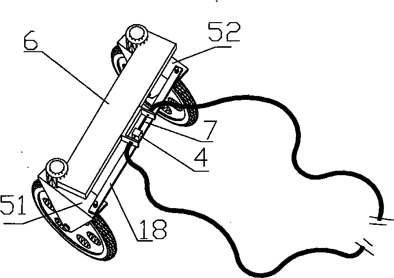
[0021] Embodiment 3: The other parts are the same as Embodiment 1, the difference is that there are 2 steering wheels, 1 steering wheel force-bearing device 1, and between the first steering wheel frame 51 and the second steering wheel frame 52 Fixed by the cross bar 18, the force bearing block 4 is fixed on the cross bar 18.


PUM


Abstract

The invention discloses a connection structure between a steering wheel and a direction controlling device. The connecting structure comprises at least one steering wheel force-bearing device and direction control limitation plate, wherein the direction control limitation plate is fixed on a main body of an automobile; the steering wheel force-bearing device comprises a force-bearing block limitation frame and a force-bearing block, wherein the force-bearing block is arranged in the force-bearing block limitation frame, the force-bearing block is fixedly arranged on a wheel carrier of the steering wheel, and the force-bearing block limitation frame is fixed on the main body of the automobile; a shaft sleeve of the steering wheel is fixed on the main body of the automobile; a steel cable passes through the direction control limitation plate and the force-bearing block limitation frame respectively, and the direction controlling device and the at least one force-bearing block are connected in series by the steel cable to form a loop; and the steel cable between the direction control limitation plate and the force-bearing block limitation frame is sleeved with a limitation sleeve pipe. The connecting structure has the advantages that: by adjusting the direction controlling device, the force-bearing block on the wheel carrier of the steering wheel can be drawn by the steel cable, so that the direction of the steering wheel can be adjusted.

Description

technical field [0001] The invention relates to a connection device, in particular to a connection structure between a steering wheel and a direction control device. Background technique [0002] The existing direction control device on the vehicle includes a steering wheel or a steering handle and a steering wheel. Taking the steering wheel as an example, the steering wheel is connected with the steering wheel through a rotating shaft assembly. During the running of the vehicle, the driver controls the direction of the steering wheel by turning the steering wheel. In order to achieve the purpose of controlling the direction of travel of the vehicle. The existing connection structure between the steering wheel and the direction control device is a mechanical hard connection, which is relatively complicated and has high manufacturing cost, and the parts cannot be folded. Contents of the invention [0003] The technical problem to be solved by the present invention is to pr...

Claims


Application Information

Patent Timeline
Patent Type & Authority Applications(China)
IPC IPC(8): B62D3/02
Inventor 吴炳发
Owner 董振丰
Why Eureka
Try Eureka