

Valve
A technology for valves and valve stems, which is applied in the direction of sliding valves, valve devices, engine components, etc., which can solve the problems of shortened service life, increased valve core wear, leakage, etc., and achieve the effect of free opening or closing and long service life
- Summary
- Abstract
- Description
- Claims
- Application Information
AI Technical Summary
Problems solved by technology
Method used
Image

Examples
Embodiment 1
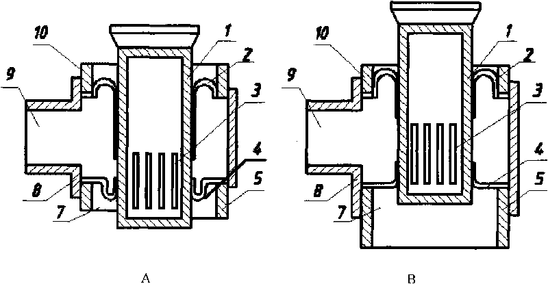
[0017] see figure 1 , including a valve body 8, a valve stem 1, an input port 9 and an output port 7, the valve stem 1 is a hollow body, a through hole 3 is arranged on the valve stem, a sealing sleeve 2 is arranged between the valve stem 1 and the upper limit ring 10, and the sealing sleeve 2, the inner edge is fixed on the valve stem 1, the outer edge of the sealing sleeve 2 is fixed on the upper inner wall of the valve body 8, and the upper limit ring 10 is clamped on the upper part of the valve body 8. A valve sleeve 4 is set between the valve stem 1 and the lower limit ring 5, the inner edge of the valve sleeve 4 is fixed on the valve stem 1, the outer edge of the valve sleeve 4 is fixed on the lower inner wall of the valve body 8, and the lower limit ring 5 is clamped on the valve body 8 lower part. A cavity is formed between the sealing sleeve 2 and the valve sleeve 4 to connect with the input port 9 . The valve stem 12, the sealing sleeve 2 and the valve sleeve 4 con...
Embodiment 2
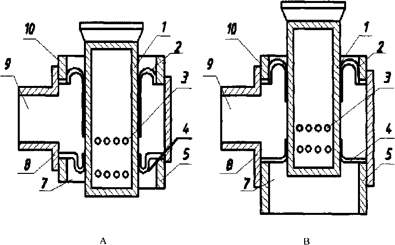
[0021] In this example, the through holes 3 are divided into two rows around the valve stem 1. The upper row of through holes is located above the inner edge of the valve sleeve 4, and the lower row of through holes is located below the inner edge of the valve sleeve 4. The rest are the same, see figure 2 .
[0022] Press the valve stem down to open the valve, such as figure 2 As shown in A, the upper row of through holes 3 enters water or air, the lower row of through holes 3 outputs water or air, and the output port 7 is an annular port between the valve stem and the valve body. Pull up the valve stem, the valve is closed, and the drain hole is closed by the valve sleeve, such as figure 2 Shown in B.
Embodiment 3
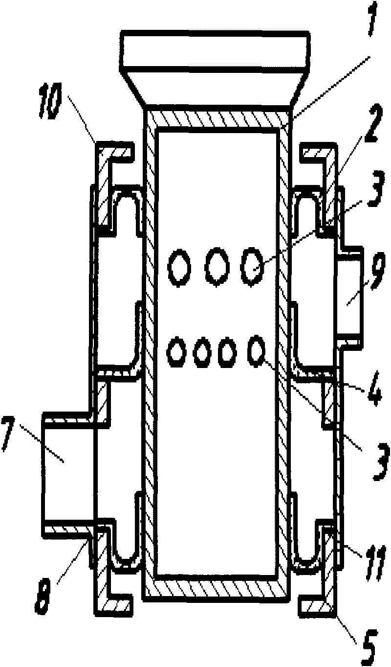
[0024] In this example, a sealing sleeve 11 is set below the valve sleeve 4, and its fixing method is the same as above. An output cavity is formed between the valve sleeve 4 and the lower sealing sleeve 11, and the output cavity is connected to the output port 7 provided on the side of the valve body.
[0025] The valve stem, valve body and limit ring in the above examples can be made of metal or plastic, and the sealing sleeve and valve sleeve can be made of elastic rubber. The sealing sleeve and the valve sleeve can be fixed by bonding, or an annular groove is opened on the valve stem and the inner wall of the valve, and the inner and outer edges of the sealing sleeve or the valve sleeve can be embedded therein. The invention can be used as a valve in liquid or gas pipeline network.
[0026] The valve of the present invention is extremely quick to open and close due to extremely small wear force and low applied pressure. The amount of water discharge can be adjusted and s...
PUM
 Abstract
Description
Claims
Application Information