
Die mold

A die-casting mold and mold technology, which is applied to the field of die-casting molds fed from the bottom of the slider, can solve the problems of increasing the cost of die-casting parts, the failure rate of castings that cannot be formed, and achieve the effect of improving internal and external quality.

Inactive Publication Date: 2010-04-28
苏州市永创金属科技有限公司
View PDF7 Cites 0 Cited by
  • Summary
  • Abstract
  • Description
  • Claims
  • Application Information

AI Technical Summary

Problems solved by technology

Today's die-casting products are becoming larger, more complex, and more precise, which puts higher demands on the structural design of die-casting molds and the design of runners and gates. Sometimes it is often due to improper design of the mold structure and die-casting runners. As a result, the casting cannot be formed and the forming defect rate is extremely high. When it cannot be compensated by other die-casting parameters, it has to use the extreme die-casting conditions, die-casting technology and many other processing technologies to remove the adverse effects, which often increases a lot of manpower and labor. The physical effect is still unsatisfactory, the mold fails prematurely, and the cost of die castings increases

Method used


Image

  • Die mold
  • Die mold
  • Die mold

Examples


Embodiment Construction

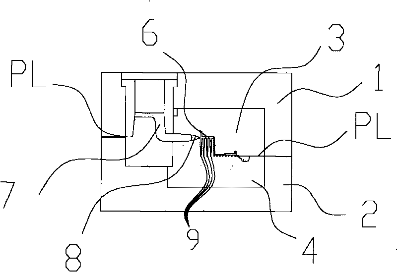
[0013] Such as figure 1 The die-casting mold of the prior art shown comprises one group of upper mold unit 1, one group of lower mold unit 2, one group of upper mold cavity unit 3 forming the cavity, and one group of lower cavity unit 4 forming the cavity. The main components and other components whose description is omitted are composed of structures and combined space types, a space 6 for forming die-casting parts, a feed channel 7 and a feed port 8 . During die-casting, the liquid raw material closes the inlet of the casting D part 9, forming a cavity space D part 9 that cannot discharge gas, and the small ribs D part 9 can only be filled in the form of pressure flow, and the forming effect is not good.

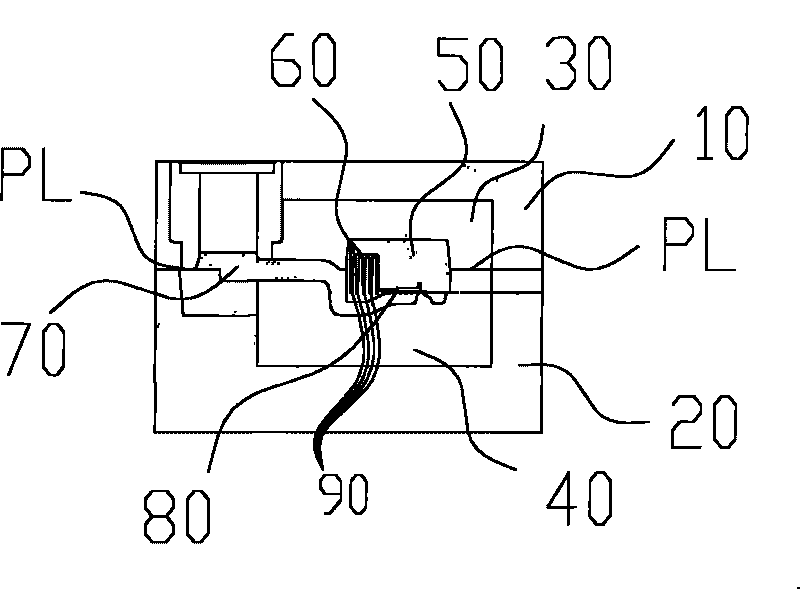
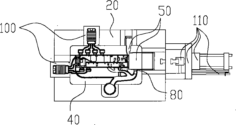
[0014] Such as figure 2 The die-casting mold of the present invention shown comprises one group of upper mold unit 10, one group of lower mold unit 20, one group of upper cavity unit 30 forming cavity, one group of lower cavity unit 40 forming cavity, one group of Slide...


PUM


Abstract

The invention relates to a die mold comprising an upper mold unit, a lower mold unit and a slide block unit, wherein the upper mold unit is provided with an upper mold cavity unit, and the lower mold unit is provided with a lower mold cavity unit; the upper mold cavity unit cooperates with the lower mold cavity unit; the slide block unit is arranged in the space formed by the cooperation of the upper mold cavity unit and the lower mold cavity unit; the bottom of the slide block unit is provided with a material inlet; the die mold also comprises an oil hydraulic slide block drawing device used for drawing out the slide block unit; and three side surfaces of the slide block unit are respectively provided with a unilateral angle of 2 degrees. The scheme of the invention comprises the tunnel-type material feeding structure on the bottom of the slide block unit of the die mold and the oil hydraulic slide block drawing device; the material inlet is arranged in the positions beneficial to filling and forming of the casting by utilizing the slide block unit; and gas in the space fills a lot of space obtaining the cavity by the substitution of the raw material, thereby overcoming many defects in form filling and die casting.

Description

technical field [0001] The invention relates to a die-casting die, in particular to a die-casting die for feeding material at the bottom of a slider, and belongs to the technical field of die-casting dies. Background technique [0002] Die casting belongs to the field of hot forming metal processing. The structural design of die casting molds has a great influence on die casting production, especially the correct setting and design of runners and gates directly affect the forming and quality of products. The design of the road not only improves the qualified rate of castings, reduces the return charge, but also prolongs the life of the mold. Today's die-casting products are becoming larger, more complex, and more precise, which puts forward higher requirements for the structural design of die-casting molds and the design of runners and gates. Sometimes it is often due to improper design of the mold structure and die-casting runners. As a result, the casting cannot be formed...

Claims


Application Information

Patent Timeline
IPC IPC(8): B22D17/22
Inventor 程斌
Owner 苏州市永创金属科技有限公司
Learn More