Lubricating device of head stock in universal machine tool

A technology of lubricating device and general machine tool, applied in metal processing machinery parts, maintenance and safety accessories, metal processing equipment, etc. Reasonable structure design, saving processing cost and improving utilization effect

Inactive Publication Date: 2012-05-09
玉环时代经典机床有限公司
View PDF0 Cites 0 Cited by
  • Summary
  • Abstract
  • Description
  • Claims
  • Application Information

AI Technical Summary

Problems solved by technology

The current way to add lubricating grease to the bedside box is to manually brush the lubricating grease on the relatively moving parts of the bedside box. The disadvantage of this method is that the brand of the grease is easy to be mistaken, which will lead to accelerated bearing wear, decreased machine accuracy, and serious Sometimes the bedside box is scrapped; at the same time, the labor intensity of the workers is high, and the grease is easy to drip and cause waste. In addition, the amount of grease added manually each time is not stable, too much will affect the operation of the bedside box and the waste of grease If it is too small, the bedside box will be worn out during the working process, and the service life of the bedside box will be reduced
[0004] When lubricating the bedside box with lubricating oil, the lubricating oil after lubrication cannot be recycled, which leads to a large waste of lubricating oil and makes the cost of lubricating oil too high
The amount of lubricating oil is not easy to control during operation, and there is no standard detection device for the specific value of lubricating oil, which will bring inconvenience to the operation
Moreover, the entire lubricating oil is not comprehensive enough when lubricating the bedside box, and only partially lubricates the bedside box, and other parts of the bedside box will be severely worn during work due to lack of lubrication.
Furthermore, the entire lubrication process is cumbersome to operate and the work efficiency is low

Method used


Image

  • Lubricating device of head stock in universal machine tool
  • Lubricating device of head stock in universal machine tool
  • Lubricating device of head stock in universal machine tool

Examples


Embodiment Construction

[0035] The following are specific embodiments of the present invention combined with the accompanying drawings to further describe the technical solutions of the present invention, but the present invention is not limited to these embodiments.

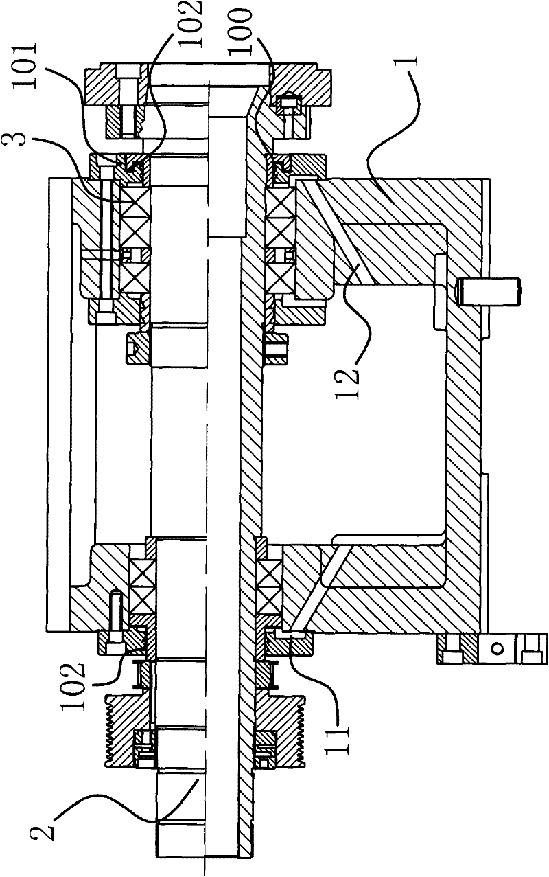
[0036] Such as figure 1 with figure 2 As shown, the headbox in a general-purpose machine tool includes a box body 1, a drive shaft 2 axially fixed on the box body 1 and capable of rotating in the circumferential direction, and 5 bearings 3 between the box body 1 and the drive shaft 2. The drive shaft 2 Wear in the box 1, such as Figure 5 As shown, two bearings 3 are installed at one contact point of the transmission shaft 2 and the box body 1, and three bearings 3 are installed at the other contact point, and the transmission shaft 2 is inserted in the bearing 3.

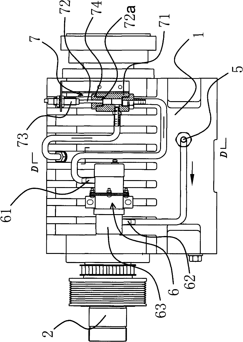
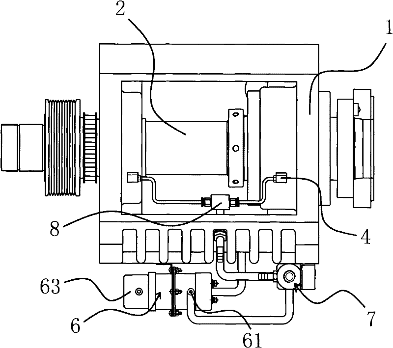
[0037] Such as image 3 As shown, the lubrication device is arranged on the box body 1, and includes a lubrication pump 63 with an oil supply port 61 and an oil return port 62 ...


PUM


Abstract

The invention provides a lubricating device of a head stock in a universal machine tool, belonging to the field of mechanical technology. The lubricating device solves the problems that the existing lubricating device of the head stock can not recycle lubricating oil, and is complicated in the operation of lubricating process and low in working efficiency. In the lubricating device of the head stock in the universal machine tool, the head stock comprises a box body, a transmission shaft which is fixed on the box body along the axial direction and can rotate along the circumferential direction, and a plurality of bearings positioned between the box body and the transmission shaft; the lubricating device is arranged on the box body and comprises a plurality of oil inlet holes which are arranged on the box body and communicated with the positions where the bearings are arranged, and an oil return hole that is arranged on the box body and leads the lubricating oil to be recycled; and an oil supply mechanism is arranged between the oil inlet holes and the oil return hole. The lubricating device has the characteristics of recycling lubricating oil as well as being high in lubrication utilization rate and good in lubrication effect.

Description

Technical field [0001] The invention belongs to the technical field of machinery, and relates to a lubricating device for a headstock, in particular to a lubricating device for a headstock in a general-purpose machine tool. Background technique [0002] In order to reduce the coefficient of friction between the various parts of the headbox in general machine tools and reduce power, while protecting the various parts of the headbox from damage and maintaining the life of mechanical accuracy, the headbox will be lubricated during work. Lubrication methods are known as grease lubrication, air-air lubrication, oil mist lubrication, jet lubrication, and the like. In the grease lubrication method, the amount of lubricating oil supplied to the machine tool depends on the content of the lubricating oil contained in the grease enclosed in the machine tool. In the oil-air lubrication method, the oil mist lubrication method and the spray lubrication method, the lubricating oil supply to the...

Claims


Application Information

Patent Timeline
Patent Type & Authority Patents(China)
IPC IPC(8): B23Q11/12
Inventor 叶国斌
Owner 玉环时代经典机床有限公司
Why Eureka
Try Eureka