Blast furnace roof material distributing device

A material distribution device, blast furnace technology, applied in the direction of bell and funnel arrangement, etc., can solve the problems of hydraulic oil compressibility, lower motion accuracy, harsh conditions such as lubrication and cooling, and increase the motion clearance of supporting rings and other parts, etc., to achieve motion Uniform and reliable, easy to use and maintain, long service life

Active Publication Date: 2010-05-05
WISDRI ENG & RES INC LTD
View PDF1 Cites 14 Cited by
  • Summary
  • Abstract
  • Description
  • Claims
  • Application Information

AI Technical Summary

Problems solved by technology

[0003] Now, the PW type bellless top distributor is commonly used in blast furnaces. The rotation and up and down overturning of the distribution chute are respectively realized by two motors driving the planetary gear differential reduction transmission mechanism. Although the operation is stable and accurate, but Due to the complex mechanism and high precision requirements for parts manufacturing, the manufacturing cost is high. At the same time, the planetary gears have strict requirements on lubrication, cooling and other conditions during operation. When the temperature of the top of the blast furnace is too high, jamming will occur. It is difficult to repair or replace when a component fails
[0004] There is also a distributor driven by a hydraulic cylinder (seeing CN85109284A), the tilting of its distribution chute is to lift the support ring by three hydraulic cylinders, and then utilize the connecting rod mechanism to complete the tilting of the chute. Although this distributor is simple in principle, three It is difficult to synchronize two hydraulic cylinders. In actual use, the movement clearance of parts such as support rings is increased, which will inevitably reduce its transmission accuracy, and the compressibility of hydraulic oil will also reduce its movement accuracy.
Obviously, since the chute is very long, a small swing angle will cause a large displacement of the chute outlet

Method used


Image

  • Blast furnace roof material distributing device
  • Blast furnace roof material distributing device
  • Blast furnace roof material distributing device

Examples


Embodiment Construction

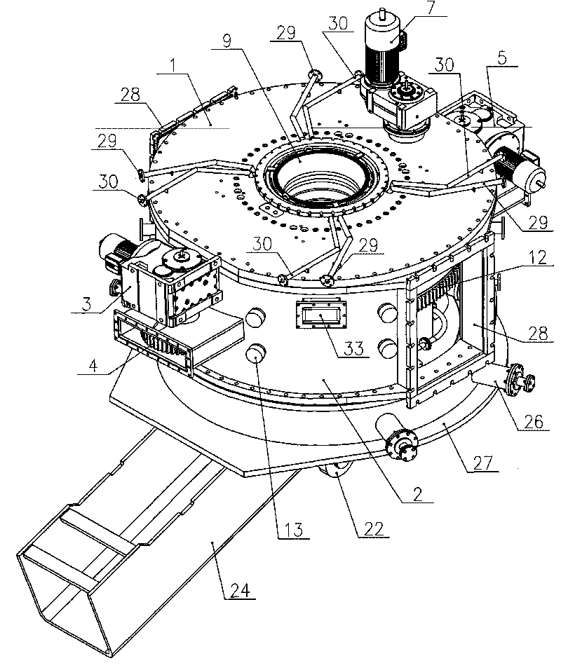
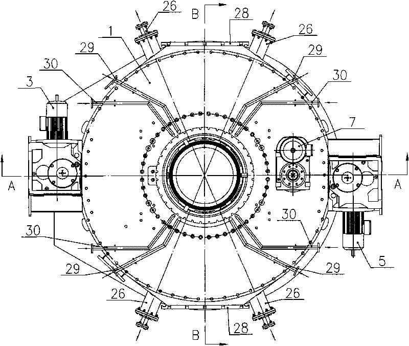
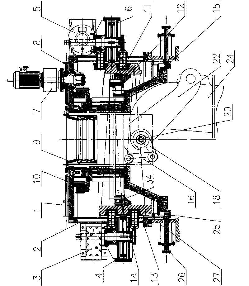
[0026] Such as figure 1 , figure 2 , image 3 , Figure 7 As shown, the blast furnace roof distributing device includes a top cover 1, a shell 2, a central throat pipe 9, a left suspension shaft 20, a right suspension shaft 21, a left swing arm 22, a right swing arm 23, a chute 24, a rotating mechanism, Tilting mechanism; the shell 2 is fixedly connected with the furnace top steel ring 27, the top cover 1 is located on the upper end of the shell 2, and the top cover 1 is fixedly connected with the shell 2; the middle part of the top cover 1 is provided with a center throat installation hole, and the center The upper end of the throat pipe 9 is located in the central throat pipe installation hole and is fixedly connected with the top cover 1, and the output port at the lower end of the central throat pipe 9 is positioned above the input port of the upper end of the chute 24 (that is, the material passing through the central throat pipe 9 can enter chute 24), the left end of...


PUM


Abstract

The invention relates to a blast furnace roof material distributing device which is characterized by comprising a top cover, a shell, a center throat pipe, a left suspension shaft, a right suspension shaft, a left movable arm, a right movable arm, a chute, a rotating mechanism and a tilting mechanism, wherein the shell is fixedly connected with a steel ring of a furnace roof, and the top cover is fixedly connected with the shell; an output opening at the lower end of the center throat pipe is arranged above an input opening at the upper end part of the chute; the left end at the upper part of the chute is clamped on the left movable arm, and the right end at the upper part of the chute is clamped on the right movable arm; the left movable arm is fixedly connected with the left suspension shaft by a spline, and the right movable arm is fixedly connected with the right suspension shaft by a spline; the left suspension shaft and the right suspension shaft are respectively connected with a rotating cylinder of the rotating mechanism by bearings; the left suspension shaft is fixedly connected with a left crank of the tilting mechanism, and the right suspension shaft is fixedly connected with a right crank of the tilting mechanism. The invention has the characteristics of simple mechanical drive principle, flexible material distribution, high running precision, reliable operation, convenient use and maintenance and long service life.

Description

technical field [0001] The invention relates to a blast furnace top material distribution device. Applied to blast furnace roof cloth, or similar process requirements of other shaft furnaces. Background technique [0002] During blast furnace smelting, the charge falls into the chute from the central throat, and according to the process requirements, the charge is distributed into the furnace by the chute in single-ring, multi-ring, fixed-point, fan-shaped, spiral, center coke and other distribution methods, which requires the distribution of The chute of the machine should have rotating motion and overturning motion. [0003] Now, the PW type bellless top distributor is commonly used in blast furnaces. The rotation and up and down overturning of the distribution chute are respectively realized by two motors driving the planetary gear differential reduction transmission mechanism. Although the operation is stable and accurate, but Due to the complex mechanism and high prec...

Claims


Application Information

Patent Timeline
Patent Type & Authority Applications(China)
IPC IPC(8): C21B7/20
CPCC21B7/20
Inventor 盛正平邵远敬周强叶理德胡雪萍喻道明戚波范小钢刘菁徐时栋田兆营刘斌奇田杰牟丹唐恩
Owner WISDRI ENG & RES INC LTD
Why Eureka
Try Eureka