
Fault diagnosing method and device

A diagnostic method and fault technology, applied in the field of communication, can solve problems such as environmental damage, failure to realize automatic recovery, positioning, etc.

Inactive Publication Date: 2010-05-12
NEW H3C TECH CO LTD
View PDF0 Cites 7 Cited by
  • Summary
  • Abstract
  • Description
  • Claims
  • Application Information

AI Technical Summary

Problems solved by technology

[0008] However, when using the command line to determine the fault point, maintenance personnel need to be trained to master the command line provided during the test; the command line requires manual operation, and the command results also need to be manually confirmed. For simple faults that are easy to recover, manual testing is also required. Intervention, automatic recovery cannot be achieved
And if the fault causes the communication device to restart, the problem environment will be destroyed. At this time, the problem cannot be located using the command line

Method used


Image

  • Fault diagnosing method and device
  • Fault diagnosing method and device
  • Fault diagnosing method and device

Examples


Embodiment Construction

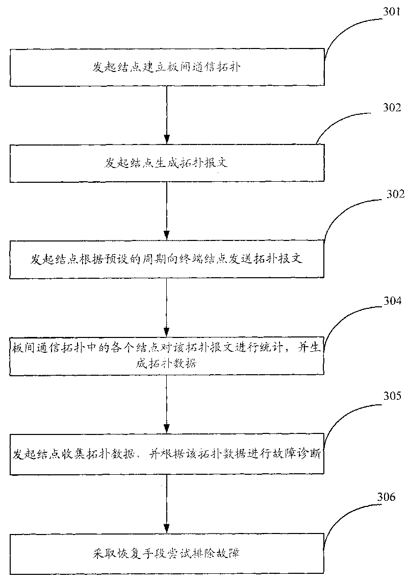
[0057] The core idea of ​​the present invention is that by generating and sending topology messages to each node in the frame device at the initiating node, each node in the frame device generates topology data according to the topology message, and the initiating node The topology data corresponding to each node is collected, so that the initiating node can perform fault diagnosis according to the topology data corresponding to each node, and diagnose the faulty node and link. Thus, the automatic diagnosis process of communication failure between boards is realized without manual intervention.

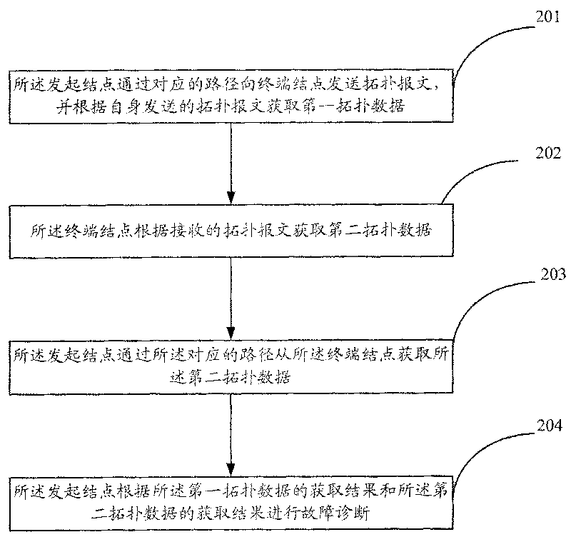
[0058] like figure 2 As shown, it is a fault diagnosis method proposed by the present invention, which is applied to a frame-type device including an initiating node and a terminal node, and the initiating node and the terminal node pass through the frame-type device Backplane connection, the initiating node and each terminal node form a path on the backplane, and the method include...


PUM


Abstract

The invention discloses a fault diagnosing method which comprises the following steps: an initiating node sends a topological message to a terminal node through a corresponding path and acquires first topological data according to the sent topological message; the terminal node acquires second topological data according to the received topological message; the initiating node acquires the second topological data from the terminal node through the corresponding path; and the initiating node conducts fault diagnosis according to the acquisition result of the first topological data and the acquisition result of the second topological data. In the invention, automatic diagnosis course of communication fault between plates is realized, with full automation, and without manual intervention.

Description

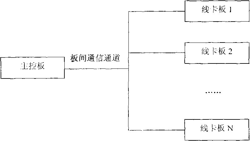
technical field [0001] The invention relates to the field of communication technology, in particular to a fault diagnosis method and device. Background technique [0002] In current communication equipment, a multi-board design structure is usually adopted, and information exchange is performed between each board through an inter-board communication channel. Wherein, on a communication device, an inter-board communication channel is a path for exchanging information between individual boards, and consists of a group of nodes and links connecting these nodes. [0003] like figure 1 As shown, it is a multi-board design mode corresponding to the main control board and the line card board, wherein there may be multiple main control boards, and each main control board can be connected to multiple line card boards through the inter-board communication channel. [0004] During the operation of communication equipment on the network, if there is an inter-board communication failur...

Claims


Application Information

Patent Timeline
Patent Type & Authority Applications(China)
IPC IPC(8): H04L12/26H04L12/24
Inventor 戴霖
Owner NEW H3C TECH CO LTD
Learn More