
Printing apparatus and printing method

A printing device and printing head technology, applied in the directions of printing devices, printing, electrical components, etc., can solve the problems of heavy user burden, limited inspection accuracy, and difficulty in maintaining the quality of inspection results stably, and achieve the effect of high-precision judgment.

Inactive Publication Date: 2010-05-26
SEIKO EPSON CORP
View PDF1 Cites 3 Cited by
  • Summary
  • Abstract
  • Description
  • Claims
  • Application Information

AI Technical Summary

Problems solved by technology

However, in the inspection method in which the user simply observes the content of the printed image, the burden on the user is heavy, and it is difficult to maintain the quality of the inspection results stably, and the inspection accuracy is of course limited.

Method used


Image

  • Printing apparatus and printing method
  • Printing apparatus and printing method
  • Printing apparatus and printing method

Examples


Embodiment Construction

[0031] Hereinafter, embodiments of the present invention will be described with reference to the drawings.

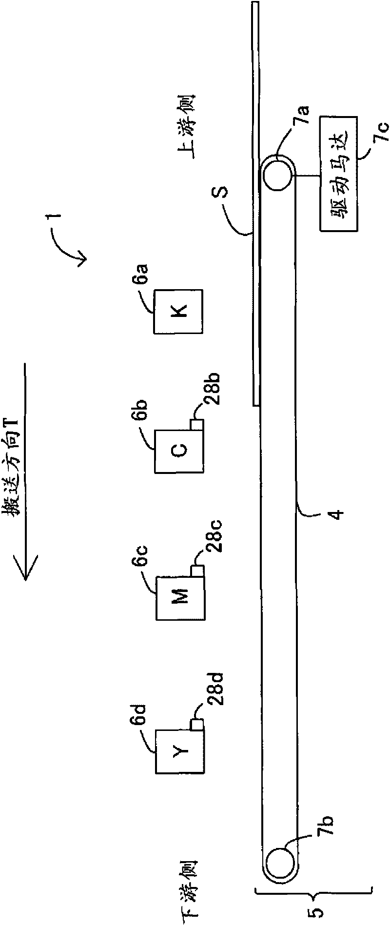
[0032] figure 1 A part of the configuration of an inkjet printer (hereinafter simply referred to as a printer) 1 according to the present embodiment is schematically shown. figure 1 The configuration of the printer 1 viewed from the side is shown. The printer 1 corresponds to an example of the printing device of the present invention. In the printer 1 , a plurality of print heads 6 a , 6 b , 6 c , and 6 d (print head groups) are arranged at predetermined intervals in a conveyance direction of paper S (print medium) (direction T indicated by arrows in the figure). In this embodiment, the print heads 6 a to 6 d are fixed inside the printer 1 .

[0033] The print heads 6a to 6d correspond to a plurality of ink colors used by the printer 1. For example, the print head 6a located on the most upstream side in the transport direction is used to eject black (K) ink, and is l...


PUM


Abstract

The invention provides a printing apparatus and a printing method capable of obtaining a printing resultant by which the quality of an image can be easily checked. An uppermost stream side print head prints on a margin area a reference timing pattern indicating an ink ejection timing for an image forming area by the uppermost stream side print head, and when an ink ejection timing for the image forming area by the print head corresponding to an image detection unit that detects the reference timing pattern is controlled based on the detection of the reference timing pattern by the image detection unit, the print head corresponding to the image detection unit that performs the detection prints on the margin area a checking timing pattern indicating the ink ejection timing by the print head corresponding to the image detection unit that performs the detection.

Description

technical field [0001] The invention relates to a printing device and a printing method. Background technique [0002] Conventionally, there has been proposed a recording head (also referred to as a line head) in which a plurality of nozzles are arranged so as to cover the maximum recording width of the printing medium in a direction perpendicular to the direction in which the printing medium moves (the width direction of the printing medium). type print head) is fixed to the state of the main body of the device, and ejects ink (Patent Document 1). According to this configuration, since printing can be performed only by moving the printing medium without moving the recording head, it is possible to shorten the printing time compared to a printer using a so-called serial head. [0003] Patent Document 1: Japanese Unexamined Patent Application Publication No. 6-183029 [0004] In a printer equipped with a line head as described above, a plurality of line heads (for example, ...

Claims


Application Information

Patent Timeline
Patent Type & Authority Applications(China)
IPC IPC(8): B41J2/01B41J2/21B41J29/393
CPCB41J2/145B41J2/2146H04N1/506
Inventor 田中良一海江田晃彰布川博一
Owner SEIKO EPSON CORP
Learn More