
Method and element structure for realizing optical recording and electrical reading of information

A technology of electrical readout and information light, applied in the direction of optical recording, etc., can solve the problems of long recording pulse width, low signal-to-noise ratio, slow speed, etc., and achieve the effects of improving recording speed, low cost, and simple structure and manufacturing process

Inactive Publication Date: 2010-05-26
SHANGHAI INST OF OPTICS & FINE MECHANICS CHINESE ACAD OF SCI
View PDF0 Cites 4 Cited by
  • Summary
  • Abstract
  • Description
  • Claims
  • Application Information

AI Technical Summary

Problems solved by technology

[0004] The purpose of the present invention is to overcome the shortcomings of the low signal-to-noise ratio in the detection of small area reflectivity changes in the current phase-change optical storage and the long recording pulse width and slow speed in the phase-change electrical storage, and provide a method for realizing information optical recording and electrical readout Method and its component structure

Method used


Image

  • Method and element structure for realizing optical recording and electrical reading of information
  • Method and element structure for realizing optical recording and electrical reading of information
  • Method and element structure for realizing optical recording and electrical reading of information

Examples


Embodiment Construction

[0018] The present invention will be further described below in conjunction with the embodiments and accompanying drawings, but the protection scope of the present invention should not be limited thereby.

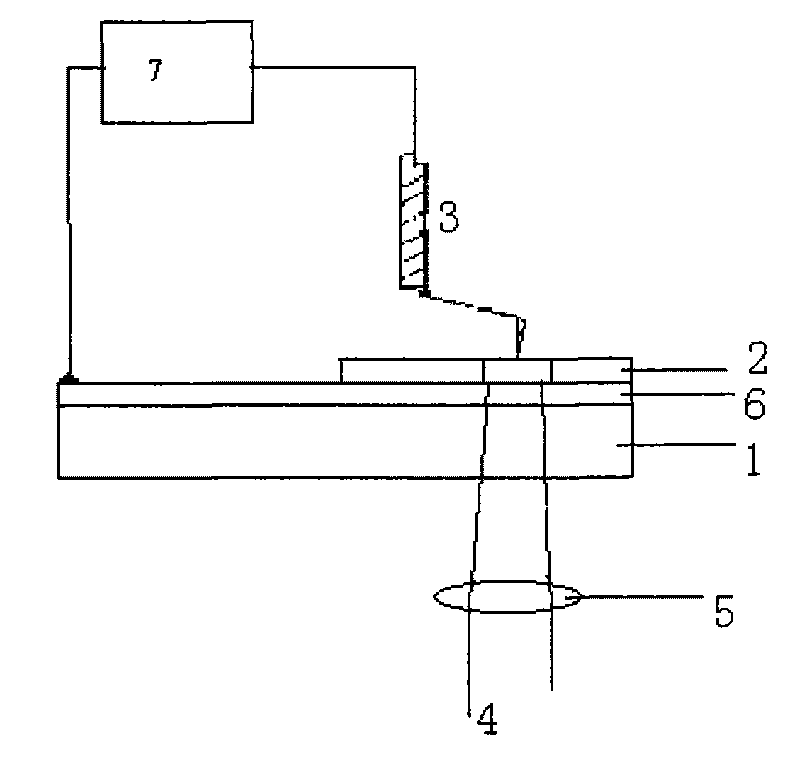
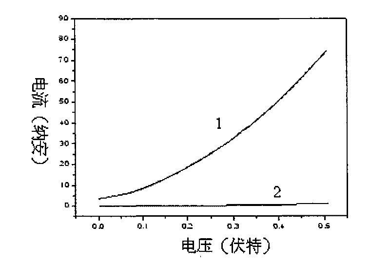
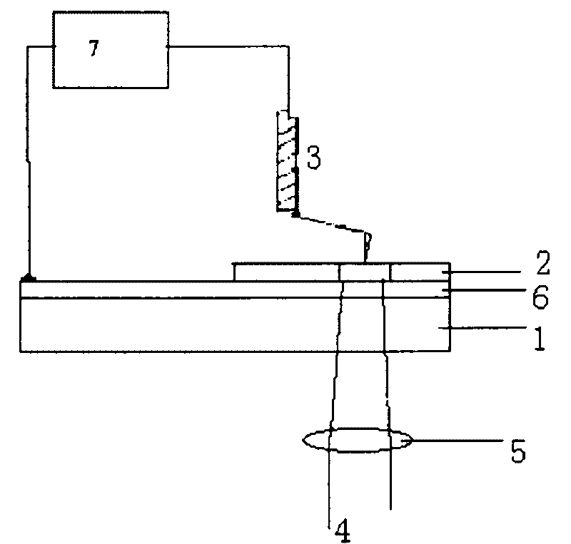
[0019] see figure 1 , figure 1 It is a principle schematic diagram of the present invention. The picosecond laser pulse 4 is focused by the focusing lens 5 and then acts on the phase-change recording layer 2 through the substrate 1 and the conductive metal layer 6 to form a phase-change recording point. The probe 3 contacts the active or non-active area of ​​the laser in the phase-change recording layer 2 . 7 is a conductive atomic force microscope. In the recording process, the ultra-short laser pulse is used to interact with the phase-change recording layer 2 to realize fast phase-change recording; in the read-out process, the probe 3 is used to contact the phase-change recording layer 2 to detect the phase-change recording points and The large difference in resistanc...


PUM

PropertyMeasurementUnit
Thicknessaaaaaaaaaa
Thicknessaaaaaaaaaa

Abstract

The invention discloses a method and an element structure for realizing the optical recording and electrical reading of information. The method is characterized by laser recording and electrical reading, wherein the laser reading is to complete information recording by forming phase change information points on a phase change thin film by using the action of a picosecond ultrashort laser pulse; and the electrical reading is to realize information reading by using a scanning probe to detect the resistance change in a phase change area. The element structure mainly comprises a transparent substrate, a metal layer serving as a lower electrode and a phase change recording layer serving as a recoding layer. The method combines the characteristics of small pulse width of the ultrashort laser pulse and dramatic resistance change before and after phase change and synchronously realizes quick recording and reading of signal with a high signal to noise ratio.

Description

technical field [0001] The invention relates to the field of photoelectric information storage, in particular to a method for realizing optical recording and electrical reading of information and its element structure. The method and structure combine the advantages of phase change material optical storage and electrical storage, and can realize fast recording and high signal-to-noise ratio signal readout. Background technique [0002] Phase change optical disc storage technology is a mature and widely used information storage technology. Phase-change optical disk storage utilizes the difference in optical reflectivity between the crystalline state and the amorphous state of the phase-change storage medium to realize recording and reading of information. The development direction of next-generation memory is high-density and large-capacity memory. In order to increase storage density, reducing the size of recording points is a direct method. However, when the information r...

Claims


Application Information

Patent Timeline
IPC IPC(8): G11B11/12
Inventor 翟凤潇王阳黄欢吴谊群
Owner SHANGHAI INST OF OPTICS & FINE MECHANICS CHINESE ACAD OF SCI
Learn More