Supercharge Your Innovation With Domain-Expert AI Agents!

Alignment mark and defect detection method

A technology for defect detection and alignment marks, which is applied in the field of defect detection and can solve problems such as numerical offsets

Active Publication Date: 2013-04-24
UNITED MICROELECTRONICS CORP
View PDF4 Cites 0 Cited by
  • Summary
  • Abstract
  • Description
  • Claims
  • Application Information

AI Technical Summary

Problems solved by technology

[0004] Therefore, the main purpose of the present invention is to provide an alignment mark and a method for detecting defects using the alignment mark, so as to improve the current situation where numerical deviations are easily generated during defect detection.

Method used


Image

  • Alignment mark and defect detection method
  • Alignment mark and defect detection method
  • Alignment mark and defect detection method

Examples


Embodiment Construction

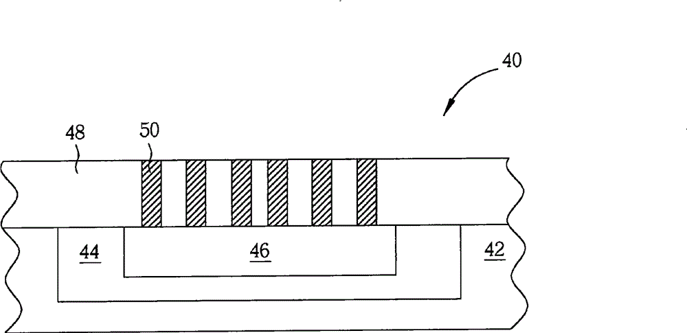
[0020] Please refer to figure 1 , figure 1 It is a schematic cross-sectional view of an alignment mark 40 according to a preferred embodiment of the present invention. like figure 1 As shown, a semiconductor substrate 42, such as a silicon wafer, is first provided. Then, an ion implantation process is performed to implant N-type dopants into the semiconductor substrate 42 to form an N-well (N-well) 44 . Next, another ion implantation process is performed to implant a P-type dopant into the formed N-type well 44 to form a shallow P+ doped region 46 in the N-type well 44 .

[0021] A dielectric layer 48 is then formed on the semiconductor substrate 42 and overlying the N- well 44 and the P+ doped region 46 . In this embodiment, the dielectric layer 48 may be composed of dielectric materials such as oxides, carbides or nitrides, or low dielectric constant materials, or any combination thereof. Then, a patterned photoresist layer (not shown) is formed on the dielectric layer ...


PUM


Abstract

The invention discloses an alignment mark and a defect detection method. The defect detection method comprises the following steps of: utilizing a first defect detection system to carry out a first defect detection step on a wafer, then carrying out a process on the wafer and utilizing a second defect detection system to carry out a second defect detection step on the wafer, wherein at least one pair of alignment marks are arranged on the wafer, the first detection step additionally comprises the step of aligning the alignment marks, and the alignment marks are reference points of the first defect detection step; the second defect detection step additionally comprises the step of aligning the alignment marks, and the alignment marks are reference points of the second defect detection step.

Description

technical field [0001] The present invention relates to an alignment mark, in particular to an alignment mark formed by an ion implantation process and a defect detection method using the alignment mark. Background technique [0002] The fabrication of semiconductor integrated circuits involves many processing steps, such as photolithography, etching, and deposition. During these steps, material is overlapped or removed from the existing layers in order to form the desired integrated circuit element. Proper alignment of the layers in various processing procedures is therefore critical. In the current semiconductor process, the marking method is mostly used to measure the alignment accuracy between different material layers. The marking method uses a specific position on a back layer to compare with another specific position on a front layer, such as making One alignment pattern on the rear layer overlaps another alignment pattern on the front layer, and the two alignment p...

Claims


Application Information

Patent Timeline
Patent Type & Authority Patents(China)
IPC IPC(8): H01L21/66H01L23/544
Inventor 周玲君陈铭聪刘喜华雷舜诚曹博昭
Owner UNITED MICROELECTRONICS CORP
Features
  • R&D
  • Intellectual Property
  • Life Sciences
  • Materials
  • Tech Scout
  • Unparalleled Data Quality
  • Higher Quality Content
  • 60% Fewer Hallucinations
Learn More