Egg beater

An egg beater and stirring piece technology, applied in the field of egg beaters, can solve the problems of unsatisfactory use, consuming a lot of time and effort, not meeting economic benefits and the like, and achieving the effect of not easy to splash

Inactive Publication Date: 2010-06-09
王吴静月
View PDF0 Cites 3 Cited by
  • Summary
  • Abstract
  • Description
  • Claims
  • Application Information

AI Technical Summary

Problems solved by technology

[0002] Generally, if you want to break up an egg, you must first prepare a container. After cracking the eggshell on a hard object, put the egg liquid into the container, and then stir the egg liquid with chopsticks. However, stirring with chopsticks cannot break the egg. The liquid is completely stirred evenly, so there are manual egg beaters and electric egg beaters on the market. Generally, manual egg beaters 1 (such as figure 1 As shown), the egg liquid 10 is placed in a container 11, the container 11 is held in one hand, and the egg beater 1 is held in the other hand, and the egg beater 1 is stirred in the container 11 in a spiral manner. The action, although the egg liquid 10 can be stirred evenly by the manual egg beater 1, it takes more time and effort to complete, and in the process of stirring, it is easy to make the egg liquid 10 due to improper force or excessive stirring action. It is splashed out of the container 11, so it is not ideal for use; in addition, the egg liquid is stirred by an electric egg beater, although the effect of saving time and labor can be achieved, but in the process of stirring the egg liquid, the egg liquid will still have some water from the container. If you only want to beat one egg at a time, the use of an electric egg beater is not economical, and it is easy to cause a waste of energy; , so research, improvement, to be the first to create the present invention

Method used


Image

  • Egg beater
  • Egg beater
  • Egg beater

Examples


Embodiment Construction

[0016] The above and other technical features and advantages of the present invention will be described in more detail below in conjunction with the accompanying drawings.

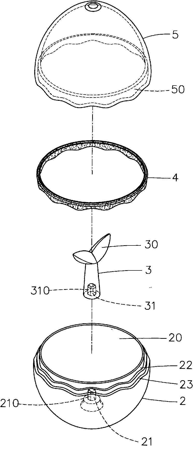
[0017] For an embodiment of the invention, please refer first to figure 2 As shown, it is mainly provided with a base 2, the base 2 is provided with a chamber 20, and a positioning boss 21 is arranged in the chamber 20, and the wall surface of the positioning boss 21 is provided with a cut surface 210 opposite to each other. The top edge of the outer wall surface of the base 2 is provided with a caulking groove 22, and the below of the caulking groove 22 is provided with an annular groove 23; A stirring member 3 is located in the chamber 20 of the base 2, and the top of the stirring member 3 is set as The leaf-shaped stirring part 30 is provided with a slot 31 at the bottom of the stirring part 3, and a cut surface 310 is provided on the wall of the slot 31; a waterproof gasket 4 is located on the socket ...


PUM


Abstract

The invention discloses an egg beater which is mainly provided with a base which is internally provided with an accommodating chamber; the accommodating chamber is internally provided with a positioning convex boss; the top edge of the outer wall face of the base is provided with a caulking groove; an annular groove is arranged below the caulking groove; the accommodating chamber of the base is internally provided with a stirring piece; the upper part of the stirring piece is set to be a stirring part and the lower part of the stirring piece is provided with a slot; the caulking groove of the base is provided with a waterproof gasket; an upper cover is arranged on the base; and the inner wall face of the upper cover is provided with an annular groove. Accordingly, a convenient and fast egg beating effect can be achieved by the following steps: opening the upper cover, knocking an egg on the stirring part of the stirring piece to crack an eggshell, enabling egg liquid to directly flow into the accommodating chamber of the base, covering the upper cover on the base, holding the base and the upper cover with hands, shaking the whole egg beater from up to down and from left to right, and stirring the egg liquid through the stirring piece in the accommodating chamber while shaking.

Description

technical field [0001] The invention relates to an egg beater, in particular to an egg beater which can break eggs evenly and conveniently. Background technique [0002] Generally, if you want to break up an egg, you must first prepare a container. After cracking the eggshell on a hard object, put the egg liquid into the container, and then stir the egg liquid with chopsticks. However, stirring with chopsticks cannot break the egg. The liquid is completely stirred evenly, so there are manual egg beaters and electric egg beaters on the market. Generally, manual egg beaters 1 (such as figure 1 As shown), the egg liquid 10 is placed in a container 11, the container 11 is held in one hand, and the egg beater 1 is held in the other hand, and the egg beater 1 is stirred in the container 11 in a spiral manner. The action, although the egg liquid 10 can be stirred evenly by the manual egg beater 1, it takes more time and effort to complete, and in the process of stirring, it is eas...

Claims


Application Information

Patent Timeline
Patent Type & Authority Applications(China)
IPC IPC(8): A47J43/14
Inventor 王吴静月
Owner 王吴静月
Why Eureka
Try Eureka