
Method for adjusting star wheel-rotor engagement accuracy of single screw rod type refrigerating compressor
A technology of refrigeration compressors and adjustment methods, which is applied in the direction of rotary piston machinery, rotary piston/swing piston pump components, mechanical equipment, etc., and can solve the problems of low product assembly efficiency, cumbersome debugging process, star wheel and screw rotor Problems such as low meshing accuracy can achieve the effects of high assembly efficiency, reduced times, and reliable operation
- Summary
- Abstract
- Description
- Claims
- Application Information
AI Technical Summary
Problems solved by technology
Method used
Image

Examples
Embodiment
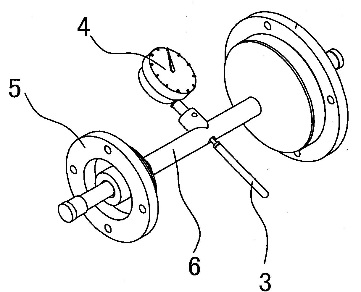
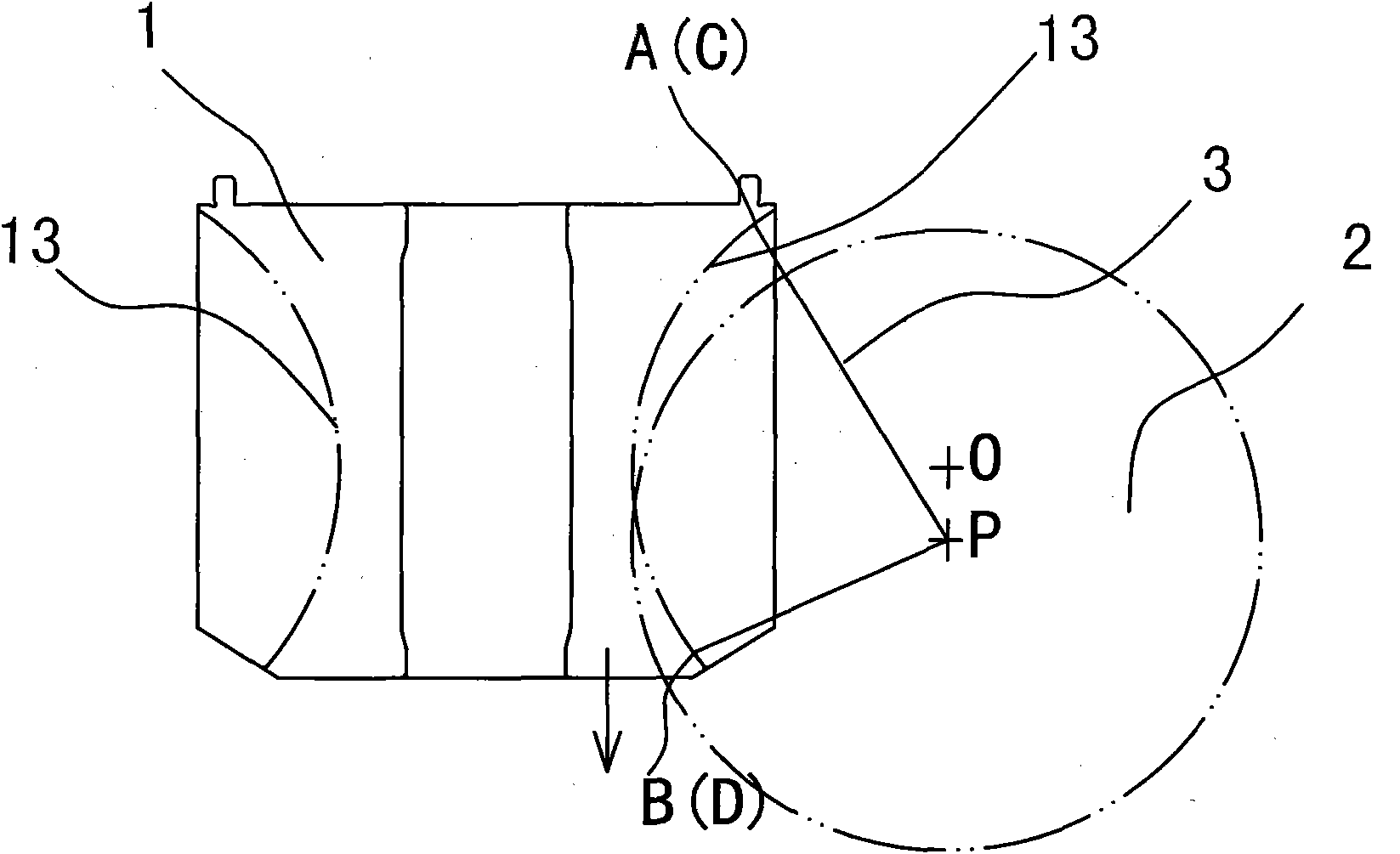
[0034] Such as Figure 2~4 As shown, a single-screw refrigeration compressor star wheel-rotor meshing precision adjustment method, before the adjustment, such as figure 2 As shown, a centering tool is produced, which is composed of two flanges 5, a rotating shaft 6, a dial indicator 4 and a centering needle 3, and the rotating shaft 6 is rotatably connected between the two flanges 5, The dial indicator 4 is arranged in the middle of the rotating shaft 6 , and its probe end is perpendicular to the rotating shaft 6 and fixedly connected with the aligning needle 3 .
[0035] The steps of the adjustment method are as follows:
[0036] (1) Put the main shaft component composed of screw rotor 1, main shaft 8, bearing 9 and bearing housing 10 into the housing 7 from one end of the housing 7, and the shaft shoulder of the bearing housing 10 is along the circumferential direction of the housing 7 opening. The mouth fits to form a pair of fixed mating surfaces perpendicular to the ax...
PUM
 Abstract
Description
Claims
Application Information