
Projecting device

A technology of projection device and body, applied in projection devices, optics, instruments, etc., can solve the problems of complex structure, bulky and bulky internal components of projectors, and unstable projection images.

Inactive Publication Date: 2011-07-27
HONG FU JIN PRECISION IND (SHENZHEN) CO LTD +1
View PDF0 Cites 0 Cited by
  • Summary
  • Abstract
  • Description
  • Claims
  • Application Information

AI Technical Summary

Problems solved by technology

[0003] Existing projector structures use large high-voltage halogen bulbs or high-pressure gas discharge bulbs as projection light source components, which must be coordinated with large high-voltage lamp circuits and heat dissipation systems, thus making the internal components of the projector complex and costly. Electricity, and the volume has become relatively bulky and bulky. In addition to being inconvenient to carry around and use, it is also not easy to install and use at any time, and it has become a fixed indoor device.
[0004] However, in the existing handheld projection device, the entire structure is fixedly connected; when the projection direction needs to be changed, the user needs to change the holding position, but the slight shaking of the user will cause the projection screen to be unstable and affect the projection effect.

Method used


Image

  • Projecting device
  • Projecting device
  • Projecting device

Examples


Embodiment Construction

[0019] The present invention will be further described in detail below in conjunction with the accompanying drawings.

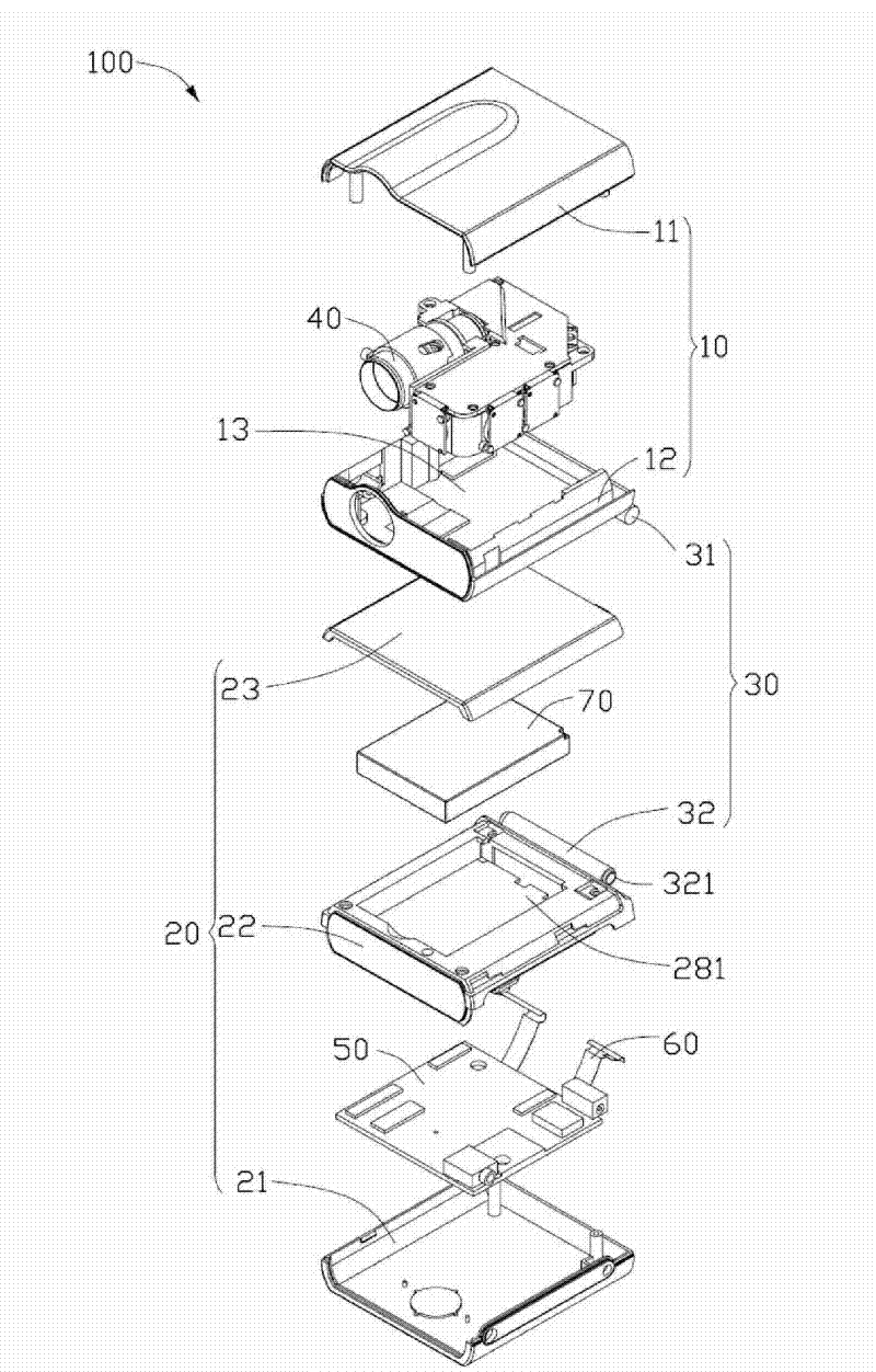
[0020] like figure 1 As shown, the projection device 100 provided by the embodiment of the present invention includes a first body 10 , a second body 20 , a rotating shaft 30 , an optical engine 40 , a printed circuit board 50 and a flexible circuit board 60 . The first body 10 and the second body 20 are movably connected through the rotating shaft 30, the optical machine 40 is housed in the first body 10, the printed circuit board 50 is housed in the second body 20, the optical machine 40 is electrically connected to the printed circuit board 50 through the flexible circuit board 60 .

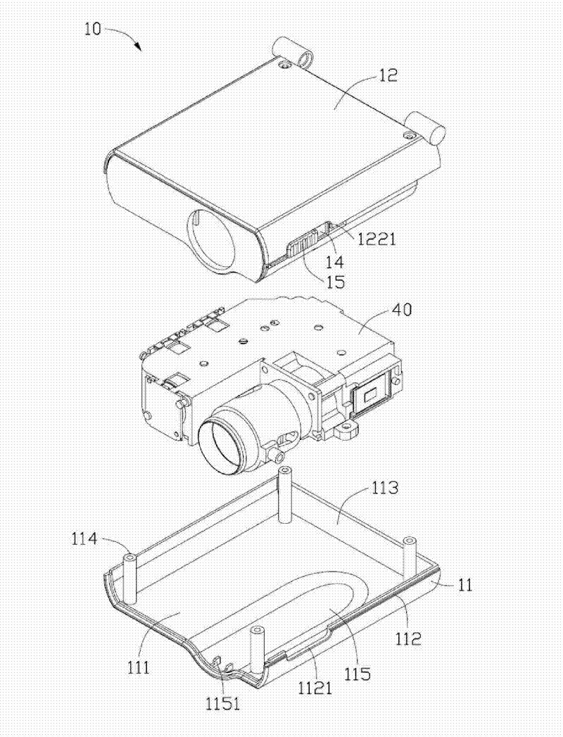
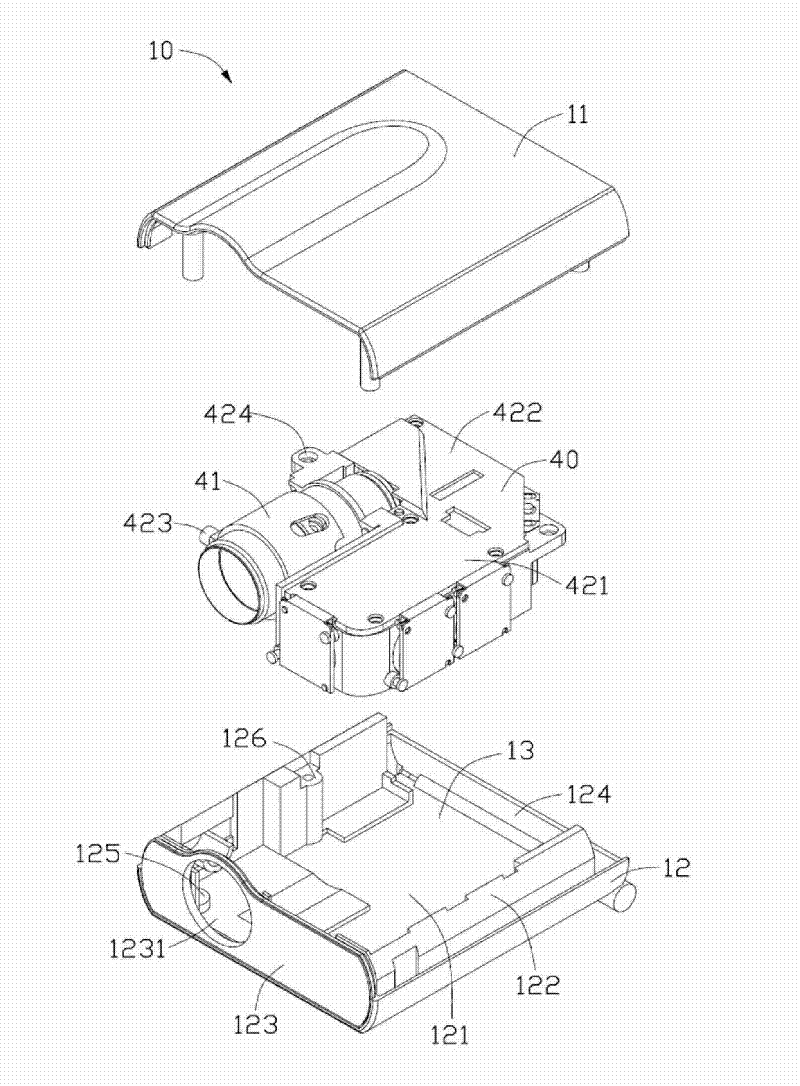
[0021] like figure 2 and image 3 As shown, the first body 10 includes a first upper cover 11 and a first lower cover 12 , the first upper cover 11 and the first lower cover 12 form an accommodating space 13 . The accommodating space 13 accommodates the optical machine 4...


PUM


Abstract

The invention provides a projecting device which comprises a first body, a second body, a rotating shaft, an optical machine, a printed circuit board and a flexible circuit board, wherein the first body is movably connected with the second body by the rotating shaft; the optical machine is contained in the first body, and the printed circuit board is contained in the second body; and the optical machine is electrically connected with the printed circuit board by the flexible circuit board; the rotating shaft includes two first sleeve shafts fixed on the first body, a second sleeve shaft fixed on the second body, a limit tooth, a spring, and a location tooth; one end of the second sleeve shaft is provided with a convex portion, and the other end is provided with a convex; a guiding groove is arranged on the limit tooth along the axial direction of the rotating shaft; the limit tooth and the spring are arranged at one end of the second sleeve shaft where the convex is, and the guiding groove of the limit tooth is clamped with the convex; the location tooth is fixed in one of the first sleeve shafts; the limit tooth and the location tooth are engaged, the convex portion of the second sleeve shaft is rotatably sleeved in another first sleeve shaft.

Description

technical field [0001] The invention relates to a projection device. Background technique [0002] The projector is widely used in the occasions of video playback, photo playback and presentation data playback, especially the projector can project and enlarge the display screen to a large-size display screen that cannot be achieved by existing TVs or monitors, making the projector suitable for A place with a large space and a large number of people. [0003] Existing projector structures use large high-voltage halogen bulbs or high-pressure gas discharge bulbs as projection light source components, which must be coordinated with large high-voltage lamp circuits and heat dissipation systems, thus making the internal components of the projector complex and costly. In addition to being inconvenient to carry around and use, it is also not easy to install and use at any time, and it becomes a fixed indoor device. [0004] However, the entire structure of the existing hand-held ...

Claims


Application Information

Patent Timeline
Patent Type & Authority Patents(China)
IPC IPC(8): G03B21/14G03B21/00
Inventor 周正鸿
Owner HONG FU JIN PRECISION IND (SHENZHEN) CO LTD
Learn More