
Vehicle lamp projection system based on millisecond wave radar

A projection system and millimeter-wave radar technology, applied in vehicle parts, vehicle maintenance, vehicle cleaning, etc., can solve problems such as failure of projection lamps, inability to interact with information, affecting pedestrians' safe walking, etc., to improve safety and improve projection. range, the effect of improving usability

Pending Publication Date: 2022-08-09
ZHEJIANG UNIV CITY COLLEGE
View PDF0 Cites 0 Cited by
  • Summary
  • Abstract
  • Description
  • Claims
  • Application Information

AI Technical Summary

Problems solved by technology

[0004] However, when the existing car light projection system is driving on an uphill road, because the projection lamp cannot adjust the direction, the projected image cannot be projected on the road surface, the function of the projection lamp will be invalid, and better information interaction cannot be achieved. , when the picture projected by the projection lamp is just projected on the pedestrian's face, the projected light will directly hit the pedestrian's eyes, which will affect the pedestrian's safe walking

Method used


Image

  • Vehicle lamp projection system based on millisecond wave radar
  • Vehicle lamp projection system based on millisecond wave radar
  • Vehicle lamp projection system based on millisecond wave radar

Examples


Embodiment Construction

[0033] In order to make it easy to understand the technical means, creative features, achieved goals and effects of the present invention, the present invention will be further described below with reference to the specific embodiments.

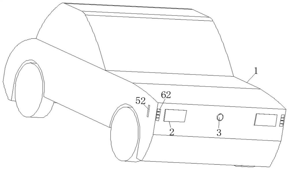
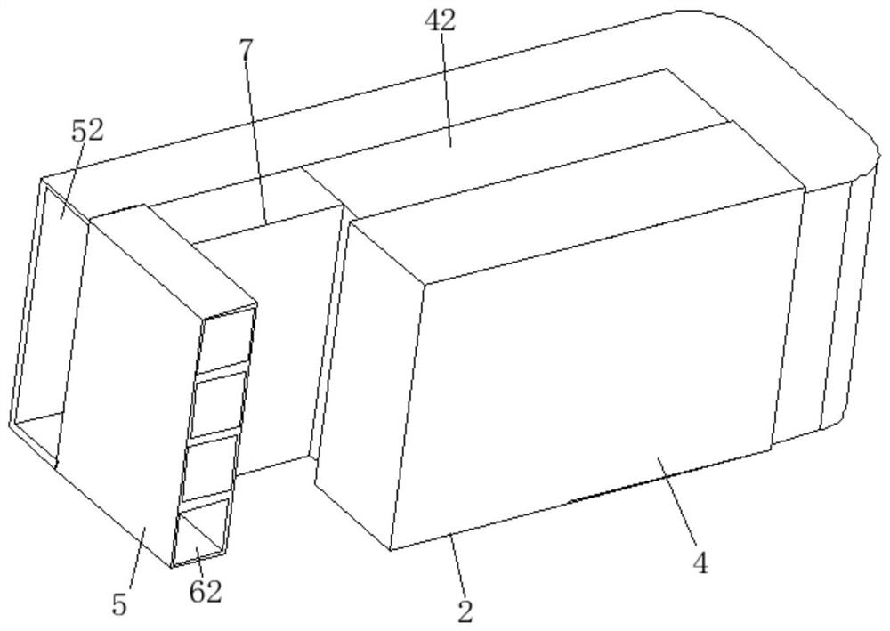
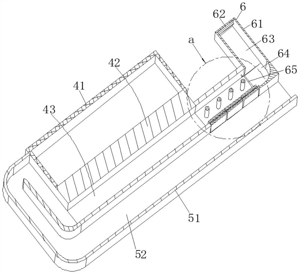
[0034] like Figure 1-Figure 11As shown, a vehicle lamp projection system based on millisecond wave radar according to the present invention includes a vehicle body 1, a vehicle lamp device 2 is installed in front of the vehicle body 1, and a millimeter wave is installed on one side of the vehicle lamp device 2 In the radar detection device 3 , the vehicle lamp device 2 includes a vehicle lamp projection device 42 , and a plurality of projection lamp devices 44 are installed on one side of the vehicle lamp projection device 42 . A lampshade 41 is fixed on one side of the vehicle lamp projection device 42 .

[0035] The projection lamp device 44 includes a projection lamp 441 , one end of the projection lamp 441 is fixed with a C-shaped frame...


PUM


Abstract

The invention discloses a vehicle lamp projection system based on millisecond wave radar, one side of a vehicle lamp projection device is provided with a projection lamp device, the projection lamp device comprises a projection lamp, one end of the projection lamp is fixedly provided with a C-shaped frame, two ends of the C-shaped frame are fixedly provided with rectangular frames, adjacent side surfaces of the rectangular frames are respectively fixedly provided with a first stress block and a second stress block, and the first stress block and the second stress block are connected with the projection lamp. A first telescopic rod is fixed to the lower end of the first stress block, a second telescopic rod is fixed to the lower end of the second stress block, wedge-shaped blocks are fixed to one end of the first telescopic rod and one end of the second telescopic rod, the horizontal ends of the wedge-shaped blocks are fixed to one side of the vehicle lamp projection equipment, and a cross-shaped rod is rotationally connected to the inner wall of the rectangular frame. The two long ends of the cross-shaped rod are rotationally connected with the inner walls of the two sides of the rectangular frame, Y-shaped rods are fixed to the two short ends of the cross-shaped rod, and one end of each Y-shaped rod is fixed to one side of the automobile lamp projection equipment. The millimeter wave radar sends out electric signals to control the first telescopic rod and the second telescopic rod to stretch out and draw back, so that the projection direction of the projection lamp is changed, the projection range can be effectively widened, informatization interaction between vehicles and between vehicles and pedestrians is promoted, and the practicability of the projection lamp is improved.

Description

technical field [0001] The invention relates to the field of vehicle lamp projection, in particular to a vehicle lamp projection system based on millisecond wave radar. Background technique [0002] As the driving assistance system of the vehicle, the lamp projection system can realize the information interaction between vehicles and between vehicles and pedestrians. [0003] The system is used for vehicles to detect pedestrians or other vehicles around them through millimeter-wave radar at night, and the relevant driving signs are projected on the road surface by the projector lamp, which is convenient for prompting pedestrians and other vehicles, thereby improving the safety of traffic driving. [0004] However, when the current vehicle lamp projection system is driving on an uphill road, since the direction of the projection lamp cannot be adjusted, the projected picture cannot be projected on the road, the function of the projection lamp will be invalid, and better infor...

Claims


Application Information

Patent Timeline
Patent Type & Authority Applications(China)
IPC IPC(8): B60Q1/26B60R16/02B60S1/54B60S1/56
CPCB60Q1/26B60R16/02B60S1/54B60S1/56B60Q2400/50
Inventor 王芳白傑黄李波
Owner ZHEJIANG UNIV CITY COLLEGE
Learn More