
Take-up winder

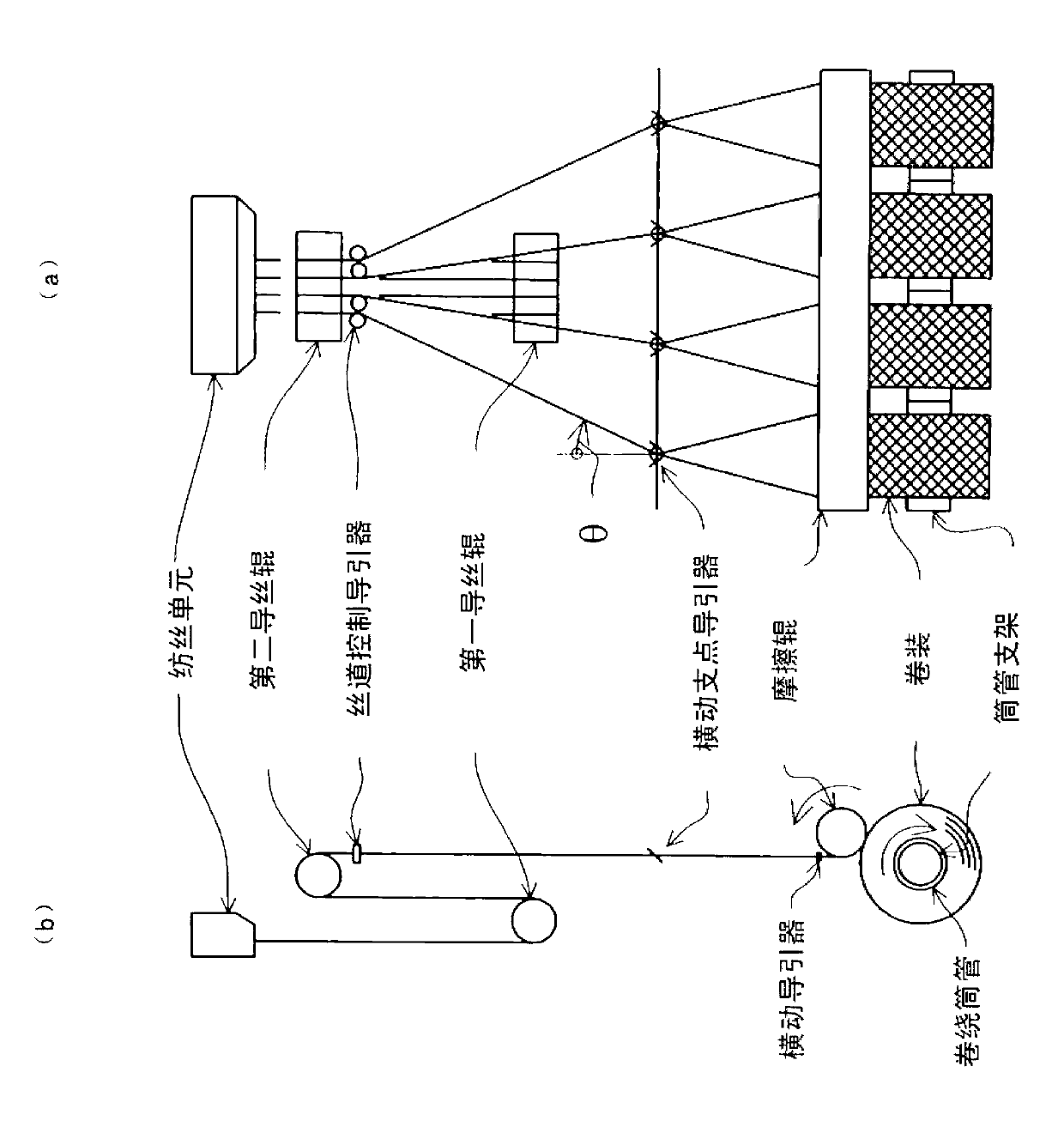
A winding machine and spinning technology, which is applied in the direction of filament generation, textile and papermaking, and conveying filamentous materials, etc. It can solve the problems of the number of guides, the lack of reference to the bending angle of the filament, and the deterioration of the filament quality, etc. question

Active Publication Date: 2013-07-10
TMT MACHINERY INC
View PDF1 Cites 0 Cited by
  • Summary
  • Abstract
  • Description
  • Claims
  • Application Information

AI Technical Summary

Problems solved by technology

However, in this case, because of the addition of a guide, there is a possibility that the resistance to the progress of the yarn will increase, and the quality of the yarn will be deteriorated.
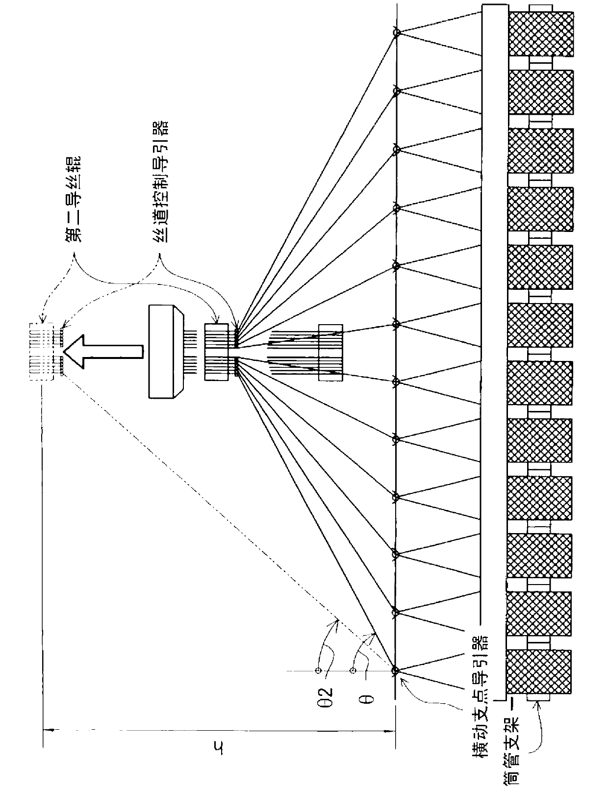
[0008] On the other hand, in the above-mentioned patent document 1, there is no mention at all of the bending angle of the thread at the traversing fulcrum guide.
[0009] Therefore, as described above, the above-mentioned bending angle θ is kept below the management upper limit bending angle θk, and the number of guides is not greater than figure 1 In the example of the prior art shown, under such preconditions, to increase the length of the bobbin support, there is no other means except to further increase the setting position of the second godet roller, and some kind of technical breakthrough is required

Method used


Image

  • Take-up winder
  • Take-up winder
  • Take-up winder

Examples


Embodiment Construction

[0027]

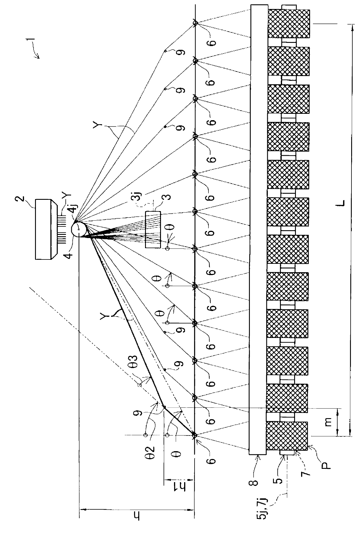
[0028] A first embodiment of the present invention will be described below with reference to the drawings. image 3 It is a front view of the spinning winder according to the first embodiment of the present invention. Such as image 3 As shown, the spinning winder 1 of this embodiment has a spinning unit 2, a first godet roll 3 and a second godet roll 4, a bobbin holder 5, and a traverse fulcrum guide 6 as main components.

[0029] The above-mentioned spinning unit 2 spins a plurality of yarns Y. In this embodiment, the yarn Y is a synthetic fiber yarn. In the present embodiment, the above-mentioned spinning unit 2 is configured to spin out 12 yarns Y at the same time.

[0030]The first godet roll 3 and the second godet roll 4 are sequentially arranged along the yarn path of the yarn Y spun by the spinning unit 2 to draw the yarn Y.

[0031] In detail, the first godet roll 3 is arranged vertically below the spinning unit 2 so that its axis direction 3j is aligne...


PUM


Abstract

An object of the present invention is to set a bend angle ¸ equal to or smaller than a management upper-limit bend angle ¸k and to reduce the need to install a second godet roller at a higher position without the need to increase the number of guides. A take-up winder 1 includes a spinning section 2, a first godet roller 3 and a second godet roller 4 arranged in order along yarn paths of yarns Y spun by the spinning section 2, a bobbin holder 5 supporting a plurality of take-up bobbins 7 around which the respective yarns Y fed from the second godet droller 4 are wound, and a plurality of traverse support point guides 6 each configured to set a traverse support point for traversing of the corresponding one of the yarns Y fed from the second godet roller 4. The plurality of winding bobbins 7 are coaxially supported by the bobbin holder 5. The axial direction 4j of the second godet roller 4 is set to be orthogonal to the axial direction 7j of the take-up bobbins 7. Each of the yarns Y bent at the respective traverse support point guides 6 by more than the management upper-limit bend angle ¸k is bent by a close guide 9 provided upstream of and close to the corresponding traverse support point guide 6.

Description

technical field [0001] This invention relates to spin winders. Background technique [0002] As such a technique, a conventional spinning winder is mentioned in Patent Document 1 (Japanese Patent Application Publication No. 2-41490). as in this application figure 1 As shown, this spinning winder adopts the method of wrapping the melt-spun synthetic fiber strands from the spinning unit (hereinafter referred to as "filaments") in turn on the first godet roll and the second On the godet roll, use the traversing fulcrum guide and the reciprocating traversing guider to wind the yarn conveyed from the second godet roll onto the winding bobbin while traversing it, thereby simultaneously Form a structure of multiple packages. [0003] Specifically, the above-mentioned winding bobbins are supported by bobbin holders, and a plurality of winding bobbins are arranged side by side along the axial direction of each winding bobbin, and the direction in which these winding bobbins are ar...

Claims


Application Information

Patent Timeline
Patent Type & Authority Patents(China)
IPC IPC(8): D01D7/00D01D11/00D01D13/02D02J1/08
CPCB65H2701/3132B65H57/08B65H57/04B65H54/20D01D13/00B65H51/06B65H54/2881
Inventor 桥本欣三
Owner TMT MACHINERY INC
Learn More