Speed reducer having function of stepless speed regulation

A technology of stepless speed regulation and reducer, which is applied in the direction of gear transmission, belt/chain/gear, mechanical equipment, etc., and can solve the problems of high technical requirements of on-site maintenance engineers, poor reliability of high-voltage frequency converters, and harmonic interference control engineers. Trouble and other problems, to achieve the effect of improving speed regulation accuracy and speed regulation stability, easy manufacturing and installation, and solving shaft end sealing problems

Inactive Publication Date: 2012-03-21
SHANDONG UNIV OF SCI & TECH
View PDF0 Cites 0 Cited by
  • Summary
  • Abstract
  • Description
  • Claims
  • Application Information

AI Technical Summary

Problems solved by technology

At present, the domestic high-voltage frequency converters mainly rely on imports, which are expensive, and the frequency converters have relatively high technical requirements for on-site maintenance engineers.
Due to the limitation of the manufacturing process of power electronic devices, the reliability of domestic high-voltage inverters is relatively poor
In addition, the unavoidable harmonic interference in the operation of the frequency converter also makes the control engineers feel troubled

Method used


Image

  • Speed reducer having function of stepless speed regulation
  • Speed reducer having function of stepless speed regulation
  • Speed reducer having function of stepless speed regulation

Examples


Embodiment 1

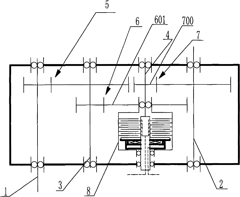
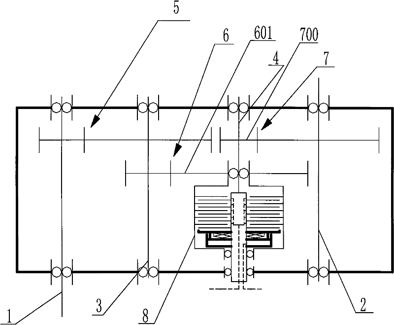
[0026] combine figure 1 , a reducer with stepless speed regulation function, including a casing, a high-speed input shaft 1 and a load output shaft 2, the axis line of the high-speed input shaft 1 and the axis line of the load output shaft 2 are arranged parallel to each other. Between the high-speed input shaft 1 and the load output shaft 2, the No. 1 intermediate transition shaft 3 and the No. 2 intermediate transition shaft 4 are sequentially arranged, and the axes of the No. 1 intermediate transition shaft 3 and the No. 2 intermediate transition shaft 4 are also connected The axis lines of 1 are arranged parallel to each other. The high-speed input shaft and the No. 1 intermediate transition shaft are connected through the first reduction gear pair 5, the No. 1 intermediate transition shaft 3 and the No. 2 intermediate transition shaft 4 are connected through the second reduction gear pair 6, and the No. 2 intermediate transition shaft The shaft 4 is connected to the load...

Embodiment 2

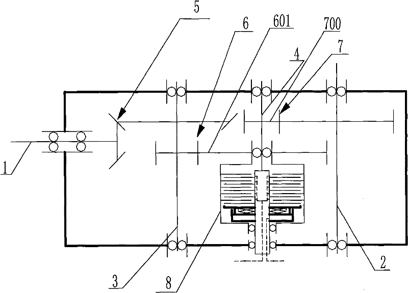
[0028] combine figure 2 , a reducer with stepless speed regulation function, including a casing, a high-speed input shaft 1 and a load output shaft 2, the axis line of the high-speed input shaft 1 and the axis line of the load output shaft 2 are arranged perpendicular to each other. Between the high-speed input shaft 1 and the load output shaft 2, the No.1 intermediate transition shaft 3 and the No. The axis lines are arranged parallel to each other. The high-speed input shaft and the No. 1 intermediate transition shaft are connected through the first reduction gear pair 5 (bevel gear pair), and the No. 1 intermediate transition shaft 3 and the No. 2 intermediate transition shaft 4 are connected through the second reduction gear pair 6 The second intermediate transition shaft 4 is connected to the load output shaft 2 through the third reduction gear pair 7 , and an oil film clutch 8 is arranged on the second intermediate transition shaft 4 . If the intermediate transition s...


PUM


Abstract

The invention discloses a speed reducer having a function of stepless speed regulation, which comprises a machine shell, a high-speed input shaft and a load output shaft. The speed reducer is characterized in that: at least one intermediate transition shaft is arranged between the high-speed input shaft and the load output shaft; the intermediate transition shaft is connected with the high-speed input shaft and the load output shaft through a speed reducing gear pair respectively; and certain intermediate transition shaft is provided with an oil film clutch. In the speed reducer, the oil filmclutch is arranged on the intermediate transition shaft, particularly on the intermediate transition shaft at a last place. Relative rotating speed between a driving friction plate and a driven friction plate of the oil film clutch is low in the process of speed regulation, and an oil film between the friction plates is in a laminar flow state, so that the speed reducer can greatly improve speed regulation precision and speed regulation stability. Meanwhile, the arrangement way also can well solve the problem of sealing shaft ends.

Description

technical field [0001] The invention relates to a speed reducer with the function of stepless speed regulation. The speed reducer combines a common speed reducer with an oil film clutch and integrates the functions of the speed reducer and the governor. Background technique [0002] At present, the stepless speed regulation of low-speed large machinery is generally completed by two independent devices, the ordinary reducer and the governor. The commonly used governors mainly include the following types: [0003] 1. Speed-regulating hydraulic coupling: It uses the high-speed rotating liquid between the pump wheel and the turbine to transfer mechanical energy from the pump wheel to the turbine, and the reducer is connected behind the turbine to drive the load to rotate mechanically. The load speed can be adjusted by adjusting the fluid filling in the turbine pump chamber. This speed regulating device is located on the high-speed shaft, and a separate reducer needs to be inst...

Claims


Application Information

Patent Timeline
Patent Type & Authority Patents(China)
IPC IPC(8): F16H3/42
Inventor 包继华姜雪于岩
Owner SHANDONG UNIV OF SCI & TECH
Why Eureka
Try Eureka