

Novel v-belt pulley structure
A technology of V-belts and pulleys, applied in belts/chains/gears, components with teeth, portable lifting devices, etc., can solve problems such as inability to realize transmission conversion, and achieve the effect of convenient transmission conversion
Inactive Publication Date: 2010-06-16
刘士民
View PDF0 Cites 1 Cited by
- Summary
- Abstract
- Description
- Claims
- Application Information
AI Technical Summary
Problems solved by technology
[0002] The V-belt pulley is an important part of the rotation system of mechanical equipment. What is known at present is that the V-belt pulley is a fixed structure. This kind of pulley cannot achieve the purpose of conversion and transmission in some places that need to be converted and rotated.
Method used
View moreImage
Smart ImageViewing Examples

Examples
Embodiment Construction
[0008] The present invention will be specifically described below in conjunction with the accompanying drawings.
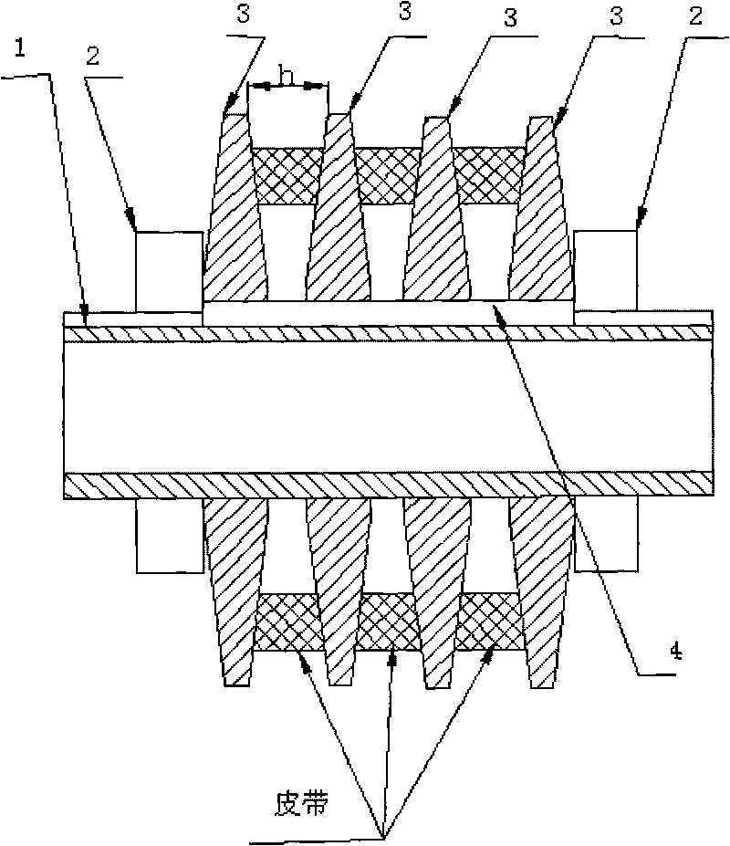
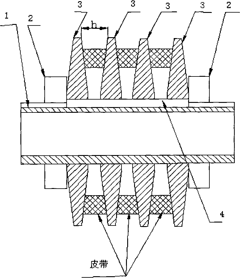
[0009] According to the number of V-belts required in the transmission, an appropriate number of transmission discs (3) are installed on the outer circle of the transmission shaft sleeve (1), and the keys (4) are used for circumferential positioning between them. Lock nuts (2) are respectively screwed on both sides of the sleeve, and the distance h between the trapezoidal grooves is adjusted so that the V-belt forms a suitable envelope radius on the pulley. In order to prevent the V-belt between the two pulleys from deflecting, the two pulleys must use the same structure.
Login to View More PUM
 Abstract
The invention relates to a novel v-belt pulley structure, according to the number of v-belts which are needed in the transmission, transmission plates (3) with proper quantity are arranged on the outer circle of a transmission shaft sleeve (1), the transmission plates (3) are located circumferentially by keys (4), locking screw nuts (2) are respectively screwed on two sides of the transmission shaft sleeve, the distance h between ladder-shaped grooves is adjusted to form a suitable enveloping radius on the belt pulley of the v-belt. In order to avoid the deflection of the v-belt between two belt pulleys, the belt pulleys need to be in the same structure. The novel v-belt pulley structure has the beneficial effects that the change of the transmission can be conveniently realized, thereby being suitable to the requirement of a transmission system which needs to change the transmission frequently.
Description
technical field [0001] The invention relates to a V-belt pulley, in particular to a novel V-belt pulley structure. It belongs to the technical field of electromechanical equipment. Background technique [0002] The V-belt pulley is an important part of the rotating system of mechanical equipment. It is known that the V-belt pulleys are all fixed structures. This kind of pulley cannot realize the purpose of conversion and transmission in some places where conversion and rotation are required. Contents of the invention [0003] The object of the present invention is to provide a new type of V-belt pulley structure, this kind of pulley can achieve the purpose of speed change only after making corresponding adjustments in places where speed change is required. [0004] The technical solution adopted to solve the technical problem is: install a number of rotating discs whose electric cross-sections are opposite isosceles trapezoids, and install them on the rotating shaft sleev...
Claims
Login to View More Application Information
Patent Timeline
 IPC IPC(8): F16H55/42
Inventor刘士民
Owner刘士民