System for monitoring auxiliary engine state

A technology of equipment status and monitoring system, applied in the field of measurement and control systems, can solve problems such as labor-intensive, difficult to ensure the reliability of industrial field equipment, equipment maintenance, and increase labor costs, so as to avoid data loss.

Inactive Publication Date: 2010-06-16
四川中鼎自动控制有限公司
View PDF0 Cites 8 Cited by
  • Summary
  • Abstract
  • Description
  • Claims
  • Application Information

AI Technical Summary

Problems solved by technology

But up to now, in the state monitoring of industrial site auxiliary equipment, the traditional manual on-duty method is still used, and the operation status of various auxiliary equipment on the industrial site is monitored manually, various data are recorded, and faults are manually performed. Diagnosis, equipment overhaul, management and maintenance, etc., not only consume labor and increase labor costs, but also the accuracy, reliability and real-time performance of monitoring results are poor. It is difficult to ensure the reliability of industrial field equipment operation and the effective targeting of equipment maintenance. sex

Method used


Image

  • System for monitoring auxiliary engine state
  • System for monitoring auxiliary engine state

Examples


Embodiment 1

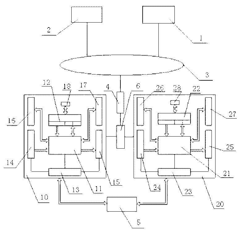
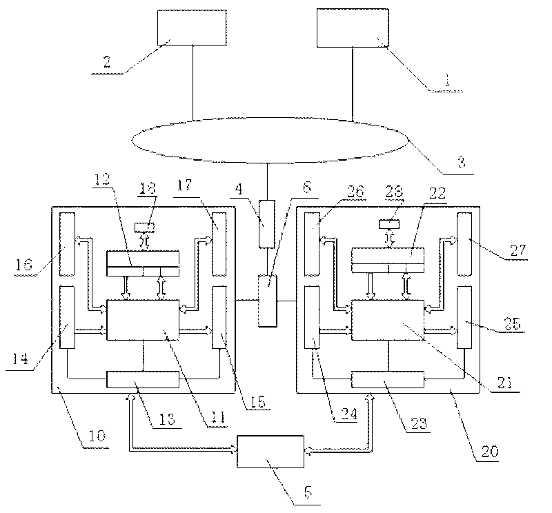
[0014] Embodiment one: if figure 1 As shown, a state monitoring system for auxiliary equipment includes: a computer 1, a data server 2, an Ethernet 3, a network switch 4, an active / standby switching device 6, a first programmable controller 10 and a second programmable controller 20 , both the first programmable controller 10 and the second programmable controller 20 are connected with the main / standby switching device 6, the main / standby switching device 6 is connected to the Ethernet 3 through the network switch 4, and is connected to the computer 1 and the computer connected to the Ethernet 3 The data server 2 is connected, and both the first programmable controller 10 and the second programmable controller 20 are connected with the industrial field auxiliary equipment 5 .

[0015] Because the main-standby switching device 6 has multiple serial ports and Ethernet ports, it is connected with two sets of programmable controllers with serial ports and Ethernet ports respective...

Embodiment 2

[0040] Embodiment 2: The difference from Embodiment 1 is that there is no active-standby switching device 6 as one of the hardware in the system, the first programmable controller and the second programmable controller are connected to the network switch, and are connected to the Ethernet through the network switch , to connect with computer and data server. The active / standby switching of two sets of programmable controllers is realized through logic programs in the two sets of programmable controllers.


PUM


Abstract

The invention discloses a system for monitoring auxiliary engine state, comprising a computer and two sets of programmable controllers; the two programmable controllers are connected with industrial field auxiliary engine equipment through respective I/O module, are connected with a network switch, are accessed into an Ethernet through the network switch, and are connected with a computer accessed into the Ethernet and a data server. The system of the invention has the beneficial effects that as the two sets of the identical programmable controllers are utilized for switching the master station and the slave station, once the master station appears control or communication faults, the slave station automatically switches into the master station to realize data mutual transmission and synchronization function. When the original slave station switches into the mater station, the computer also automatically connects to a new master station seamlessly, and realizes data synchronization; users can not perceive the changes of switching and synchronization to achieve redundancy function in real meaning.

Description

technical field [0001] The invention relates to a measurement and control system, in particular to a state monitoring system for industrial site auxiliary equipment. Background technique [0002] The main equipment in the field of industrial control is generally expensive. After the failure or accident of the main equipment, it will cause great economic losses to the enterprise, and the maintenance cost of the equipment is high, and the labor intensity is high. Therefore, the enterprise is very concerned about the health of the main equipment. At present, there are many condition monitoring systems applied to the main equipment. [0003] In order to ensure the safe and stable operation of main and auxiliary equipment on the industrial site, reduce the number of planned maintenance of auxiliary equipment, and improve the availability of auxiliary equipment, the operation status of auxiliary equipment should be highly valued by enterprises. Enterprises urgently need to improv...

Claims


Application Information

Patent Timeline
Patent Type & Authority Applications(China)
IPC IPC(8): G05B19/048G05B19/418
CPCY02P90/02Y02P90/80
Inventor 唐洪王春林何军杨勇彭进廖永刚黄平
Owner 四川中鼎自动控制有限公司
Why Eureka
Try Eureka