Supercharge Your Innovation With Domain-Expert AI Agents!

Commutator and manufacturing method thereof

A commutator and commutator segment technology, which is applied in the field of motors, can solve the problems of difficult to achieve large-sized annular varistor, difficult to ensure electrical connection, difficult to weld, etc., to achieve easy implementation and easy welding. The effect of resistance and good EMC level

Inactive Publication Date: 2014-03-12
JOHNSON ELECTRIC GUANGDONG CO LTD
View PDF7 Cites 0 Cited by
  • Summary
  • Abstract
  • Description
  • Claims
  • Application Information

AI Technical Summary

Problems solved by technology

[0005] A defect of the solution shown in Figure 21 is that after the wire end 4' of the coil is welded to the hook 32' of the commutator segment, an oxide film will be formed on the surface of the wire end 4' and the hook 32' to prevent the wire end 4' from and hook 32' are oxidized
Because the oxide film is non-conductive, it is difficult to weld the electrode 51' of the ring varistor to the hook 32'; even if the welding is successful, it is difficult to ensure that the two are electrically connected
In addition, the annular varistor 5' is installed on the outer surface of the commutator segment 3', which is easily damaged by the outside
[0006] In addition, in the solution shown in Figure 21, the inner ring of the annular variable resistor is larger than the cylinder surrounded by the commutator segments. If the number of commutator poles is large or the output is large, a large-volume annular variable resistor will be required. resistance, and the existing ring varistor sintering technology is difficult to achieve large size ring varistor

Method used


Image

  • Commutator and manufacturing method thereof
  • Commutator and manufacturing method thereof
  • Commutator and manufacturing method thereof

Examples


no. 1 example

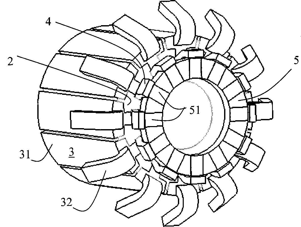
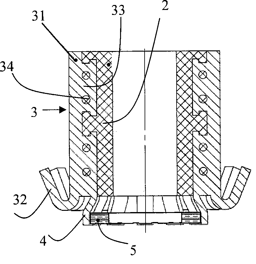
[0023] figure 1 and figure 2 They are respectively a three-dimensional schematic diagram and a longitudinal sectional view of the commutator in the first embodiment of the present invention. refer to figure 1 and figure 2 , the commutator includes a commutator base 2 , several commutator segments 3 , several connecting segments 4 and ring resistors 5 . Wherein, the commutator base body 2 is a columnar insulator, and there is an axial through hole in the middle of the commutator base body 2 for installing the rotating shaft of the rotor. Each commutator segment 3 is spaced apart from each other to achieve insulation. The commutator segment 3 includes a main body 31 and a hook 32. The inner side of the main body 31 has a protruding embedded part 33, and the embedded part 33 is fixedly embedded in the The commutator base 2, the hook 32 is fixed to the hooked end of the commutator segment main body 31 and protrudes outward. In this embodiment, the connecting piece 4 and the...

no. 2 example

[0035] Figure 8 and Figure 9 are respectively an exploded view and a three-dimensional schematic view of the commutator of the second embodiment of the present invention, Figure 10 and Figure 11 They are the front view and the A-A longitudinal section view respectively.

[0036] refer to Figure 8 to Figure 11 , The main difference between the commutator of this embodiment and the commutator of the first embodiment lies in the shape of the connecting piece 4 . In this embodiment, the connecting piece 4 and the commutator piece 3 are formed separately, and the width of the connecting piece 4 is similar to the width of the main body 31 of the commutator piece 3 . The fixed end of the connecting piece 4 is fixed to the inner side of the hooked end of the main body 31 of the connecting piece 3 by welding. The ring varistor 5 is installed in the area surrounded by the protruding end of the connecting piece 4 . The extended end of the connecting piece 4 is narrowed to form...

no. 3 example

[0047] The present invention has been described in detail above with reference to the accompanying drawings. In the above-mentioned embodiment, the connecting piece 4 is mounted to the inner side of the commutator piece 3, but the present invention is not limited to this case. For example, as an alternative solution, the connecting piece 4 can be coplanar with the commutator piece 3, or as a whole. The manufacturing method of this replacement commutator will be briefly described below in conjunction with the accompanying drawings.

[0048] First, if Figure 19 As shown, some teeth 35 and some connecting pieces 4 are cut out on one side of the sheet 7, the teeth 35 and connecting pieces 4 are arranged in a staggered manner, and the number of teeth 35 and connecting pieces 4 is equal to that of the desired commutator piece. quantity, then bend the teeth 35 towards one side to form hooks, and roll the sheet into a ring with the hooks facing outwards to obtain a commutator ring....


PUM


Abstract

The invention discloses a commutator and a manufacturing method thereof. The commutator comprises an insulating columnar commutator base body (2), a plurality of commutator segments (3) arranged on the commutator base body (2), a plurality of connecting pieces (4) and an annular rheostat (5), wherein one end of each commutator segment (3) is provided with a hook (32); the annular rheostat (5) is arranged at the end of the commutator with the hook; and the end of each commutator segment (3) provided with the hook is electrically connected to a corresponding electrode (51) of the annular rheostat (5) through one connecting piece (4). The commutator of the invention is arranged in a rotor after the annular rheostat is arranged and fixed, and then a wire terminal of a coil is welded on the hooks of the commutator segments, so the commutator avoids the influence of an oxide film, makes the welding of the annular rheostat convenient and is easy to implement. In addition, the annular rheostats are electrically connected with the ends of the commutator segments (3) provided with the hooks, so the annular rheostat is closer to the coil and is of a higher EMC level.

Description

technical field [0001] The invention relates to the field of motors, in particular to a commutator of the motor and a method for manufacturing the commutator. Background technique [0002] Fig. 20 is a schematic diagram of a conventional commutator. As shown in Figure 20, the commutator includes a commutator base 2' and several commutator segments 3'. Wherein, the commutator base body 2' is an insulating hollow cylinder, and the commutator base body 2' is concentrically fixedly mounted on the rotating shaft 1' of the motor rotor, and can rotate along with the rotating shaft 1'. The commutator segments 3' are evenly installed on the commutator base 2', each commutator segment 3' is insulated from each other, and a part of the commutator segment 3' is embedded in the commutator base 2' to be fixed to the commutator Device base 2'. The coil end of the commutator piece 3' has a hook 32', and the wire end 4' of the coil is welded to the hook 32'. [0003] When the commutator ...

Claims


Application Information

Patent Timeline
Patent Type & Authority Patents(China)
IPC IPC(8): H01R39/04H01R43/06
Inventor 沈延新罗庆斌
Owner JOHNSON ELECTRIC GUANGDONG CO LTD
Features
  • R&D
  • Intellectual Property
  • Life Sciences
  • Materials
  • Tech Scout
  • Unparalleled Data Quality
  • Higher Quality Content
  • 60% Fewer Hallucinations
Learn More