Multi-carrier-based method for mapping resource
A resource mapping and multi-carrier technology, applied in the field of multi-carrier-based resource mapping, can solve problems such as not being able to meet needs
- Summary
- Abstract
- Description
- Claims
- Application Information
AI Technical Summary
Problems solved by technology
Method used
Image
Examples
Embodiment 1
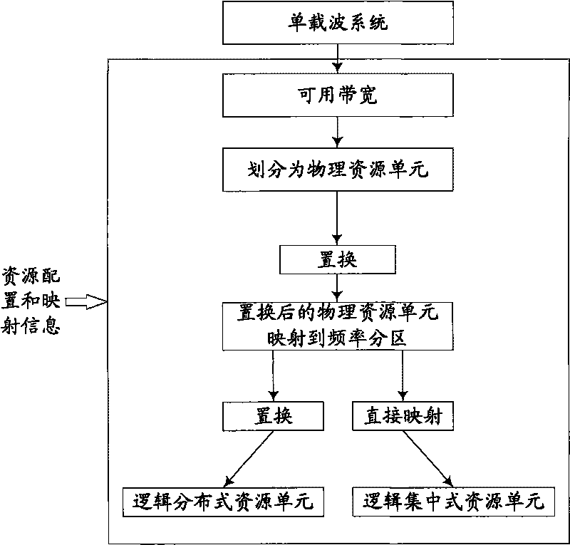
[0041] In this embodiment, a resource mapping method is provided. Figure 4 A schematic diagram of the implementation process of the method is given, such as Figure 4 As shown, it can be roughly achieved by the following operations:
[0042] Step 402, perform a first permutation operation on the n physical resource units included in the available subcarriers in units of n1 physical resource units; taking the first permutation operation using uniform extraction permutation as an example, when performing the permutation operation, will be The n1 physical resource units are used as a unit to extract physical resource units from the n physical resource units at equal intervals.
[0043] Step 404: Map the n physical resource units after the first permutation operation to multiple frequency partitions according to the frequency partition configuration information, specifically, the frequency partition configuration information here is the number of frequency partitions and the phy...
example 1
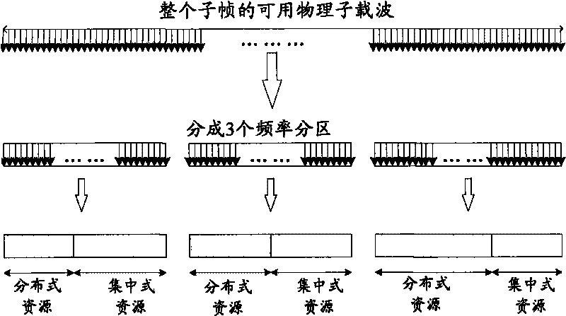
[0048] In this example, the frequency partition configuration information is as follows: (1) divide the subframe into 3 frequency partitions, that is, the number of frequency partitions is 3, (2) frequency partition 1 includes a centralized resource group and a distributed resource group The centralized resource group and the distributed resource group respectively contain 4 physical resource units; frequency partition 2 includes a centralized resource group and a distributed resource group, wherein the centralized resource group contains 10 physical resource units, and the distributed The centralized resource group contains 2 physical resource units; the frequency partition 3 only includes a centralized resource group, and the centralized resource group contains 4 physical resource units; (3) the centralized resource groups in frequency partition 2 and frequency partition 3 are both It is required to contain 4 consecutive physical resource units.
[0049] Figure 5 The resou...
example 2
[0057] In this example, the frequency partition configuration information is as follows: (1) divide the subframe into 3 frequency partitions, that is, the number of frequency partitions is 3; (2) frequency partitions 1, 2, and 3 respectively include a centralized resource group and A distributed resource group, the centralized resource group and the distributed resource group respectively contain 8 physical resource units; (3) The centralized resource groups in frequency partitions 1, 2, and 3 are required to contain 4 consecutive physical resource units .
[0058] Image 6 The resource mapping process of the 10MHz wireless communication system in the embodiment of the present invention is described. In combination with the above-mentioned frequency partition configuration information, the Image 6 The process shown is described. Among them, the number of FFT points of the 10MHz system is 1024, and the number of available subcarriers in the subframe is 864, which is divided ...
PUM
 Abstract
Description
Claims
Application Information
 - R&D
- Intellectual Property
- Life Sciences
- Materials
- Tech Scout
- Unparalleled Data Quality
- Higher Quality Content
- 60% Fewer Hallucinations
Browse by: Latest US Patents, China's latest patents, Technical Efficacy Thesaurus, Application Domain, Technology Topic, Popular Technical Reports.
© 2025 PatSnap. All rights reserved.Legal|Privacy policy|Modern Slavery Act Transparency Statement|Sitemap|About US| Contact US: help@patsnap.com


