
Electric ramming tool

A nail gun and nailing technology, which is applied in the field of nail guns, can solve the problems of troublesome switching operation and inability to switch modes, and achieve the effect of preventing misoperation, preventing inadvertent operation, and enhancing switching operability

Inactive Publication Date: 2010-06-16
MAKITA CORP
View PDF2 Cites 9 Cited by
  • Summary
  • Abstract
  • Description
  • Claims
  • Application Information

AI Technical Summary

Problems solved by technology

In the prior art, in order to switch the action mode, a nail gun with a dedicated switching lever is provided, but because the switching operation is cumbersome, the mode switching cannot be performed quickly

Method used


Image

  • Electric ramming tool
  • Electric ramming tool
  • Electric ramming tool

Examples


Embodiment Construction

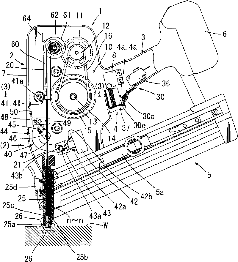
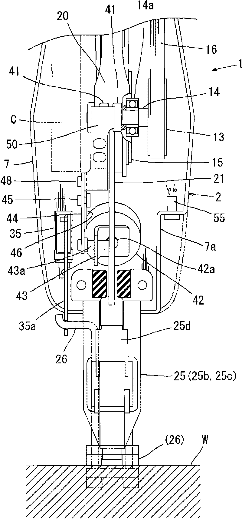
[0042] Below, according to Figure 1 to Figure 17 Embodiments of the present invention will be described. figure 1 and figure 2 The nail gun 1 of this embodiment is shown. The nail gun 1 has a body 2 , a handle 3 and a staple bin 5 .

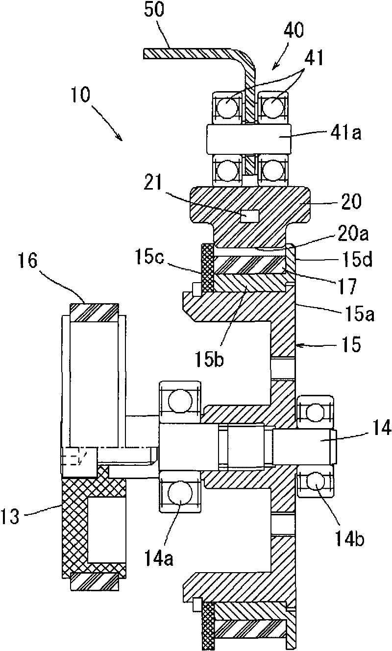
[0043] The body 2 has a substantially cylindrical body case 7, which is made of resin and divided into two parts. Inside the body case 7, a driving mechanism using a motor 11 as a driving source is incorporated. 10. A nail n is struck by the nailing mechanism 10 and driven into the material W to be nailed. Details of this driving mechanism 10 will be described later.

[0044] The handle 3 is integrated with the body 2 and protrudes from the side of the body 2 toward one side. The handle 3 is also divided into two parts and is integrated with the side part of the body shell 7 . At the base of the handle 3, a trigger 4 (trigger switch lever) and a lock lever 30 are provided. On the top of the handle 3, a rechargeable battery pack 6 is ins...


PUM


Abstract

In a conventional electric ramming tool for performing the ramming operation by using an electric motor as a drive source, operation mode is switched between a sequential ramming mode and a single ramming mode for example by switching operation of an extra switching lever and thereby the switching operation is troublesome. In the inventive electric ramming tool, operation mode is switched without requiring a troublesome operation. A lock lever (30) for preventing incorrect operation of the trigger (4) more positively is provided, and the operation mode is switched by altering the operation order of the lock lever (30) and a contact trip (26).

Description

technical field [0001] The invention relates to a nail gun used for nailing nails and other nails into a material to be nailed. The nail gun uses a motor as a driving source. Background technique [0002] For example, the nail gun usually uses compressed air as the driving source, and the piston is reciprocated by the compressed air, so as to obtain a larger impact force (air nail gun). In contrast, there is also a nail gun that uses an electric motor as a drive source to reciprocate a nailing driver (firer) to strike nails or other nails (electric nail gun). By using a DC power supply (battery) to drive the motor as the driving source, it is not necessary to connect the air hose and the compressor when the compressed air is used as the driving source. Therefore, the ease of use of the nail gun can be improved. and operability. [0003] This electric nail gun has the following basic mechanism: the drive wheel is rotated by using the motor as the driving source, and the dri...

Claims


Application Information

Patent Timeline
Patent Type & Authority Applications(China)
IPC IPC(8): B25C7/00B25C1/06
CPCB25C1/008B25C1/06
Inventor 须田秀和
Owner MAKITA CORP
Learn More