Method for tucking an end of a weft thread into a selvedge of a fabric, and pneumatic tuck-in device

A fabric and weft thread technology, applied in the field of pneumatic folding devices, can solve problems such as the complexity of driving equipment

Active Publication Date: 2010-06-16
PICANOL NV
View PDF4 Cites 12 Cited by
  • Summary
  • Abstract
  • Description
  • Claims
  • Application Information

AI Technical Summary

Problems solved by technology

The drive mechanism is relatively complex, since it needs to be precisely synchronized with the movement of the reed or with the movement of the sley

Method used


Image

  • Method for tucking an end of a weft thread into a selvedge of a fabric, and pneumatic tuck-in device
  • Method for tucking an end of a weft thread into a selvedge of a fabric, and pneumatic tuck-in device
  • Method for tucking an end of a weft thread into a selvedge of a fabric, and pneumatic tuck-in device

Examples


Embodiment Construction

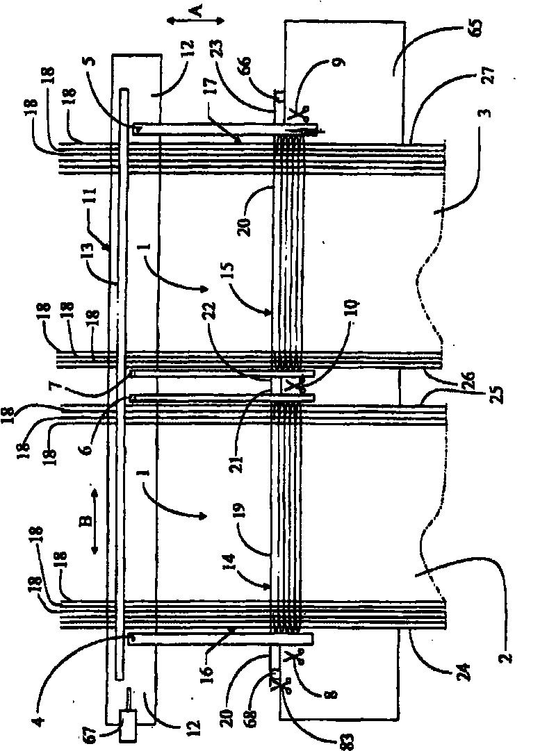
[0026] exist figure 1 In the loom shown, two pieces of fabric 2, 3 are woven next to each other. The figure shows four pneumatic tuck-in devices 4 to 7 according to the invention, more specifically one tuck-in device 4 is arranged near the insertion side 16 of the shed 1 and one tuck-in device 5 is arranged at the shed 1 Near the opposite side 17 of , the two tuck-in devices 6 and 7 are arranged between the fabrics 2, 3 adjacent to each other. A cutting device 8 is added to the tuck-in device 4 , a cutting device 9 is added to the tuck-in device 5 and a common cutting device 10 is added to the tuck-in devices 6 and 7 . The weaving machine also comprises a sley 11 comprising a sley profile 12 to which a reed 13 is attached. In this case, the tuck-in devices 4 to 7 are attached to the sley profile 12 . In this case, the cutting devices 8 to 10 are also attached to the sley profile 12 . In order to allow the insertion of weft threads, the shed 1 is formed in a known manner us...


PUM


Abstract

The invention relates to a method for tucking an end (23) of a weft thread (19) into a selvedge (27) of a fabric (3) by means of a pneumatic tuck-in device (5) which blows an end (23) of an inserted and beaten up weft thread (19) extending past a selvedge (27) of the fabric (3) into a subsequent shed (1), whereby the tuck-in device (5) is moved back and forth along the selvedge (27) of the fabric(3) in synchronization with the reed (13) and blows in of this end (23) of the beaten-up weft thread (19) into a shed (1) while the tuck-in device (5) moves back and forth along the selvedge of the fabric.

Description

technical field [0001] The invention relates to a method for tucking the ends of inserted weft threads into the selvedge of a fabric by means of a pneumatic tuck-in device which blows the ends of the weft threads which beat up at the edge of the fabric. ) and extend beyond the fabric selvedge into a subsequent shed, and the invention also relates to pneumatic tuck-in devices. Background technique [0002] Pneumatic tuck-in devices are known, for example, from US 4957144 and WO 01 / 86047 A1. In order to be able to blow the ends of the weft threads into the subsequent shed, the pneumatic tuck-in device is located at least partially on the side of the reed, in front of the beat-up thread or in front of the fabric edge. In order not to impede the beat-up movement of the reed, it is known to omit the reed in the region of the pneumatic tuck-in, allowing the reed to move along the tuck-in all the way to the beat-up line. In order not to interrupt the reed in the region of the tuc...

Claims


Application Information

Patent Timeline
Patent Type & Authority Applications(China)
IPC IPC(8): D03D47/48
CPCD03D47/48
Inventor J·彼得斯J·-M·巴梅利斯F·巴夫科普D·桑珀斯
Owner PICANOL NV
Why Eureka
Try Eureka