A material fall buffer device

A buffer device and drop technology, which is applied in the direction of conveyor objects, transportation and packaging, springs/shock absorbers, etc., can solve problems such as damaged and dropped materials, and achieve the effects of alleviating impact, reducing maintenance costs, and reducing wear and tear

Active Publication Date: 2020-04-07
HOHHOT HAI RI HAN BIOTECH CO LTD
View PDF13 Cites 0 Cited by
  • Summary
  • Abstract
  • Description
  • Claims
  • Application Information

AI Technical Summary

Problems solved by technology

[0004] The object of the present invention is to provide a kind of material fall buffering device, to at least solve the problem of broken and dropped material existing in the prior art

Method used


Image

  • A material fall buffer device
  • A material fall buffer device
  • A material fall buffer device

Examples


Embodiment 1

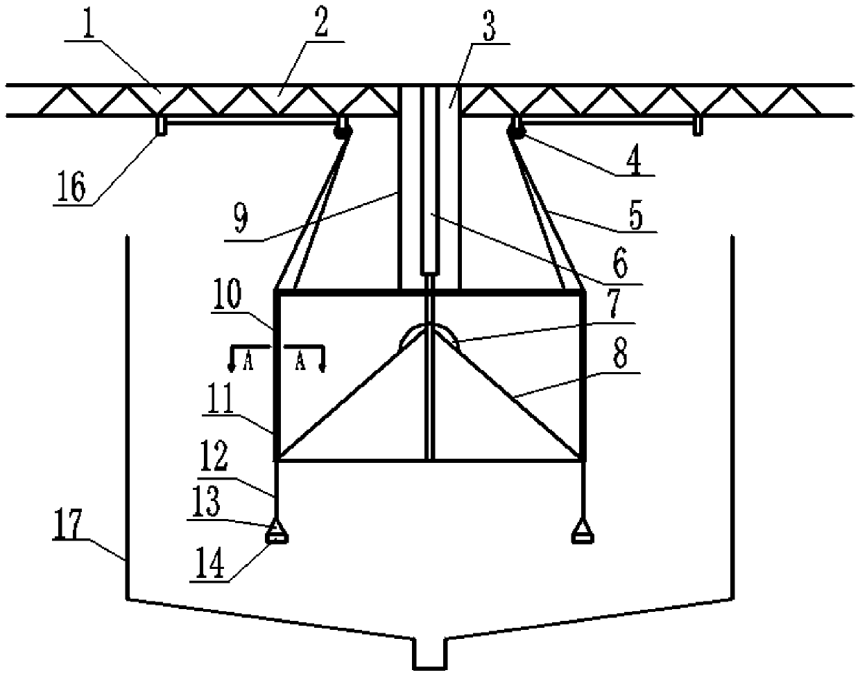
[0027] Such as Figure 1-3 As shown, the present invention provides a material fall buffer device, including: a transmission device and a lifting device, the transmission device includes a crane 1, a conveyor belt 2 is provided inside the crane 1, and gaps are provided at both ends of the crane 1, A baffle is provided at the notch, and a material guide groove 3 is provided at the baffle.

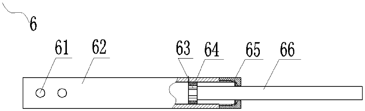
[0028] The lifting device comprises a damping device 6, a casing 10, a netway and a spring rope 5.

[0029] The network channel uses flexible network channel 9 to prevent the material from being damaged by the network channel during the falling process. The top of the flexible network channel 9 is connected to the crane 1 and is located directly below the material guide trough 3, which is used to realize the material directly passing through the material guide. The groove 3 falls into the channel of the flexible network channel 9, the bottom end of the flexible network channel 9 is connecte...

Embodiment 2

[0034] In order to achieve stable and safe lifting of the box body 10 under the traction of the spring rope 5 , the material fall buffer device provided by the present invention is provided with two spring ropes 5 on both sides of the box body 10 .

Embodiment 3

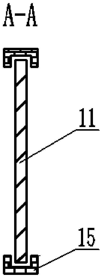
[0036] In order to realize the sliding of the box door 11 through the deformation of the rubber pad 14 due to pressure, two legs 12 are provided at the bottom of each box door 11 .

[0037] working principle

[0038] Materials such as potatoes and apples are transported to the gaps at both ends of the crane 1 through the conveyor belt 2 fixed inside the crane 1, and are blocked by the baffle, falling from the gap to the material guide trough 3, and through the material guide trough 3 to the Inside the flexible network channel 9, the material falls along the flexible network channel 9, falls on the buffer pad 7 fixed on the top of the inclined chute 8, and is cushioned, and the material slides into the box body 10 along the inclined chute 8 without damage. With the accumulation of materials, the box body 10 will become heavier and heavier, and the box body 10 will gradually move downward. , the rubber pad 14 will be deformed to generate an upward thrust, the rubber pad 14 push...


PUM


Abstract

The invention belongs to the technical field of material falling devices, and provides a material falling buffering device. The material falling buffering device comprises a conveying device and a lifting device; the conveying device comprises a crane which is internally provided with a conveying structure, and one end of the crane is provided with a material guide groove; the lifting device comprises a damping device, a box body, a net path and a pulling rope; the top end of the net path is connected with the crane and located below the material guide groove, and the bottom end of the net path is connected with the box body; the top end of the damping device is connected with the crane, and the bottom end of the damping device is connected with the box body; the pulling rope is connectedwith the crane and the box body and used for achieving ascending and descending of the box body; and the two sides of the box body are provided with box body doors so that material falling can be achieved. Meanwhile, the material falling buffering device has the characteristics of being capable of achieving ongoing non-damaging material falling through the pure mechanical structure, good in reliability, high in safety and low in using and maintaining cost.

Description

technical field [0001] The invention belongs to the technical field of material falling devices, in particular to a material falling buffer device. Background technique [0002] In processing enterprises such as potatoes and apples, the temporary storage of materials is generally in a rectangular pool with a certain height and width. Above the storage pool is a horizontal crane with a conveyor belt. The crane has two outlets. It is transported by the conveyor belt on the crane and released into the storage pool through two exits on the crane. When the material falls into the storage pool, it will collide with the bottom of the pool or the material at the bottom of the pool, causing damage to the material and affecting the quality. [0003] Therefore, in view of the above deficiencies, the present invention urgently needs to provide a kind of material drop buffering device. Contents of the invention [0004] The object of the present invention is to provide a material fal...

Claims


Application Information

Patent Timeline
Patent Type & Authority Patents(China)
IPC IPC(8): B66C1/16F16F15/023B65G47/44
CPCB65G47/44B66C1/16F16F15/023
Inventor 岳志勇杨晓霞朱明新张战勇丁惠
Owner HOHHOT HAI RI HAN BIOTECH CO LTD
Why Eureka
Try Eureka