Battery charging control device

A battery charging and control device technology, applied in battery circuit devices, circuit devices, current collectors, etc., can solve the problems of shortening battery life, reducing charging efficiency, battery charging interference, etc. The effect of reducing fluctuations

Inactive Publication Date: 2012-05-02
UNIV OF ELECTRONICS SCI & TECH OF CHINA
View PDF2 Cites 17 Cited by
  • Summary
  • Abstract
  • Description
  • Claims
  • Application Information

AI Technical Summary

Problems solved by technology

[0007] However, the battery in practical applications has loss after working for a long time. At the same time, due to the small internal resistance of the battery itself, a small change in the internal resistance of the battery will also cause a large disturbance in battery charging. At this time, the SOC (State of Charge, b

Method used


Image

  • Battery charging control device
  • Battery charging control device
  • Battery charging control device

Examples


Embodiment

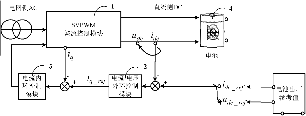
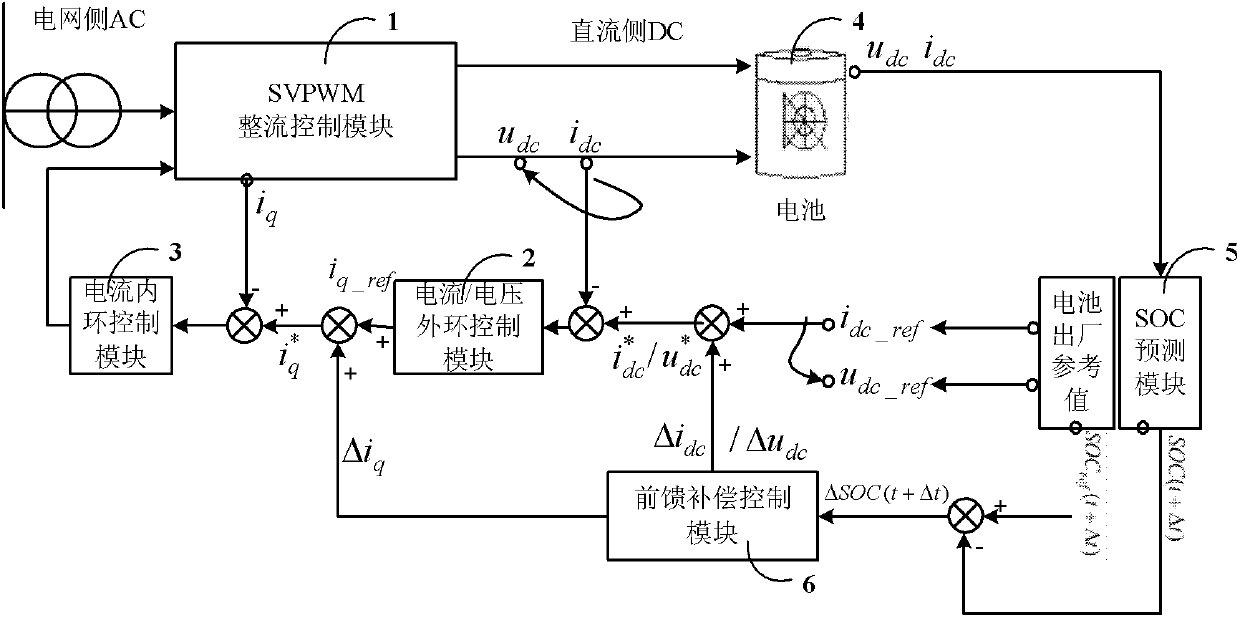
[0028] figure 2 It is a structural diagram of a specific embodiment of the battery charging control device of the present invention.

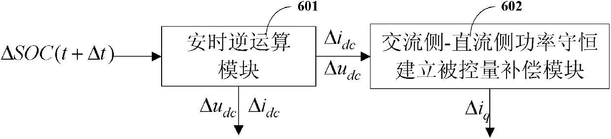
[0029] In this example, if figure 1 As shown, the battery charging control device of the present invention includes a SVPWM (Space Vector Pulse Width Modulation) rectification control module 1, a current / voltage outer loop control module 2, a current inner loop control module 3, and an SOC (State of Charge, battery state of charge) Prediction module 5, feedforward compensation control module 6.

[0030] The three-phase current and voltage on the AC side are rectified by the SVPWM rectification control module 1 to obtain the required DC current i dc / DC voltage u dc For battery charging, the DC current i of the battery factory reference value dc_ref / DC voltage u dc_ref Add reference value correction value DC current Δi dc / Reference correction value DC voltage Δu dc , get the corrected reference DC current i * dc / DC voltage u * ...

example

[0073] The battery charging control device based on SOC prediction feedforward compensation control of the present invention is applied to a specific application, and an external interference signal and an ideal battery are used to simulate an actual battery, wherein the interference signal is a variable resistor. Use 8A to charge the lithium battery with a constant current, and compare the SOC of the battery at different times.

[0074] The current change curve of the output current at the battery terminal after adding the discontinuous variable resistor interference is shown in Figure (4), and the current after adding feed-forward compensation can clearly adjust the current state and maintain a constant current state of 8A. Such as Figure 5 as shown, Figure 5 The small glitches at the set point are caused by discontinuous changes in resistance.

[0075] The SOC sampling change value of the battery is charged for a long time, and the change is as follows: Figure 6 As sh...


PUM


Abstract

The invention discloses a battery charging control device. On the basis of the prior art, a feed-forward compensating structure composed of an SOC (Silicon on Chip) prediction module and a feed-forward compensation control module is additionally arranged; by means of the SOC prediction module and the feed-forward compensation control module, reference quantity correction direct current delta idc/reference quantity correction direct-current delta udc and a controlled quantity compensation value delta iq are added in a traditional control structure so as to consider internal resistance changes of a battery in a control loop, so that the charging is more stable so as to reduce battery losses and achieve the purpose of prolonging the service life of the battery; meanwhile, because an internalloop control period is far smaller than an external loop control period, a q component iq of an alternating-current side current can be immediately modified into an alternating-current side referencecurrent value by modifying an alternating-current reference current iq_ref into iq<*>=iq_ref+delta iq, so that a target is controlled, and the fluctuations of the charging currents of the battery arereduced.

Description

technical field [0001] The invention belongs to the technical field of battery charging control, and more specifically relates to a battery charging control device. Background technique [0002] At present, the battery charging adopts PWM rectification control structure, and the space vector pulse width modulation (SVPWM) method is used to realize the control of the three-phase AC vector. The rectification control adopts the cascade control structure of the current inner loop control and the current / voltage outer loop control to achieve The purpose of outputting DC side current and voltage controllable. [0003] figure 1 It is a structural diagram of an existing battery charging control device. [0004] Such as figure 1 As shown, the battery charging control device is rectified by the three-phase AC power on the AC side through the SVPWM rectification control module 1 to obtain the required DC current i dc or DC voltage u dc , that is, the charging current or charging v...

Claims


Application Information

Patent Timeline
IPC IPC(8): H02J7/10
Inventor 邹见效郑宏徐红兵彭超
Owner UNIV OF ELECTRONICS SCI & TECH OF CHINA
Why Eureka
Try Eureka