Elevator controlling device

An elevator control device and elevator technology, applied in the field of elevator control devices, can solve problems such as passenger impact, and achieve the effects of preventing a sharp increase in braking force and mitigating the impact.

Inactive Publication Date: 2006-11-15
HITACHI LTD
View PDF1 Cites 17 Cited by
  • Summary
  • Abstract
  • Description
  • Claims
  • Application Information

AI Technical Summary

Problems solved by technology

[0009] In addition, when switching from electric braking torque control by electric motors t

Method used


Image

  • Elevator controlling device
  • Elevator controlling device
  • Elevator controlling device

Examples


no. 1 Embodiment

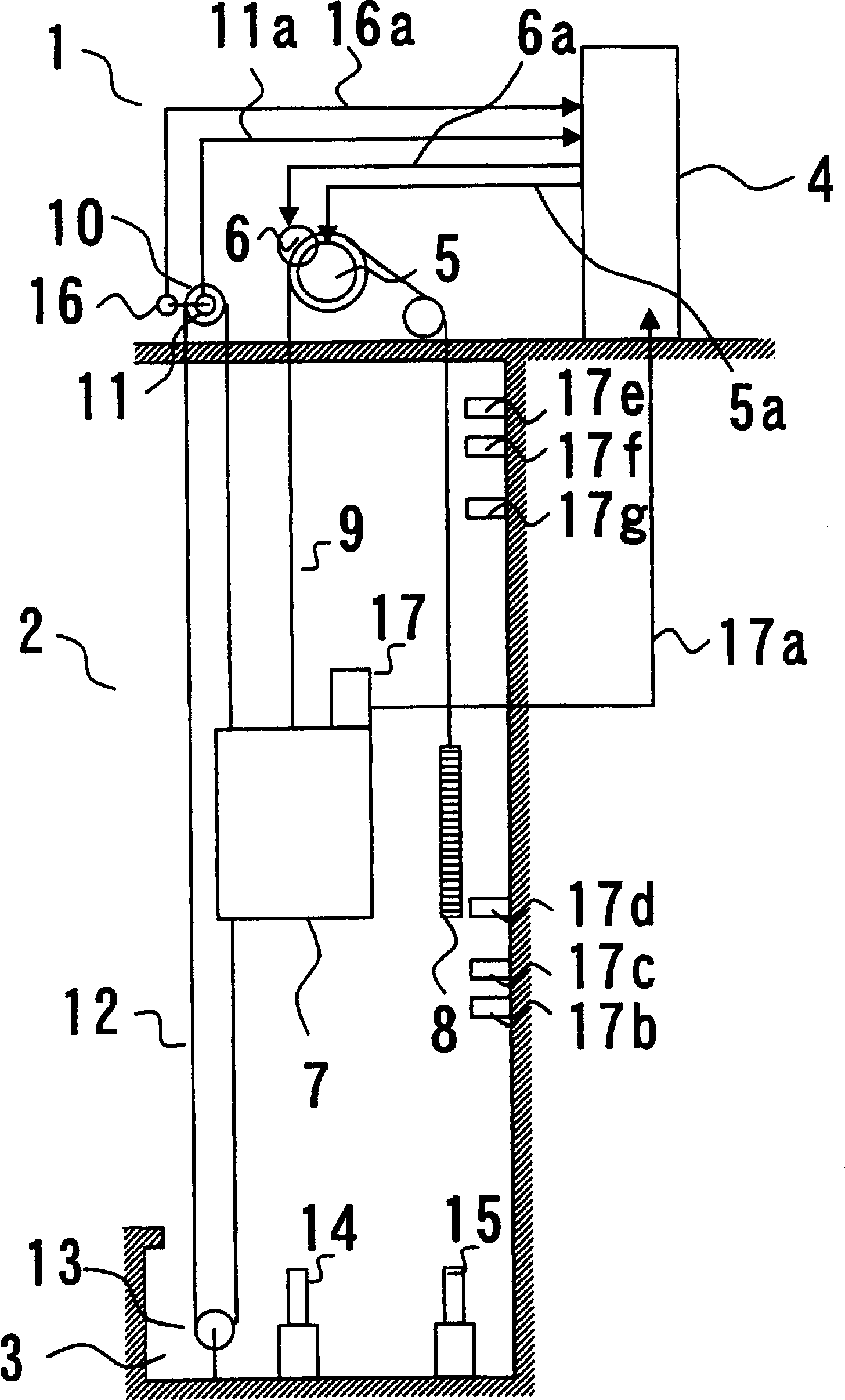
[0023] figure 1 It is a sectional view of an elevator structure provided with an elevator control device according to the present invention.

[0024] The elevator of the first embodiment is installed in a space composed of a machine room 1 , a hoistway 2 and an elevator pit 3 .

[0025] In the machine room 1, the elevator control device 4, the motor 5 of the hoist, the mechanical brake 6 of the hoist, the governor 10 of the elevator car, the speed detector 11 of the elevator car, and the movement amount detector 16 of the elevator car are installed. .

[0026] The speed detector 11 of the elevator car and the movement amount detector 16 of the elevator car are constituted by a rotary encoder or the like.

[0027] The elevator car 7, the counterweight 8, the position detection device 17 installed on the elevator car 7 and the position marks 17b-17g are arranged in the elevator passage 2, wherein the elevator car 7 and the counterweight 8 are suspended on the main sling 9 The...

no. 2 example

[0049] Figure 5 It is a structural block diagram of the motor control circuit in the second embodiment of the elevator control device according to the present invention.

[0050] The motor 5 used in this embodiment is a motor such as a permanent magnet synchronous motor having electrical characteristics such that an input line is short-circuited and a moment is generated in a rotation stop direction when the rotor rotates.

[0051] The motor control device 200 includes a motor drive circuit 202 and a short circuit mechanism 201 . The short-circuit mechanism 201 is driven by a short-circuit control signal 201 a from the terminal layer deceleration control device 100 to short-circuit the motor input lines 5 b , 5 c , and 5 d connected from the motor drive circuit 202 to the motor 5 .

[0052] In this second embodiment, when the speed of the elevator car reaches or exceeds the overspeed level 21, while outputting the brake signal 6a, the elevator stops Figure 4 The control co...

no. 3 example

[0056] In the third embodiment, the switching elements in the short-circuit mechanism 201 of the second embodiment are composed of IGBTs, etc., and before the elevator car stops at the terminal floor, the switching elements perform multiple switching actions, like the anti-lock brake of a car. The braking system acts like that.

[0057] In the third embodiment, before the elevator car stops at the terminal floor, the switching element in the short-circuit mechanism 201 is switched on and off multiple times, and the braking torque of the motor is intermittently used, so the braking force at the start of the mechanical brake operation can be prevented. The sharp increase can further ease the impact on passengers.


PUM


Abstract

An elevator control device comprising: an overspeed detection device for judging whether the speed of an elevator car at a predetermined position is less than or equal to an overspeed corresponding to a distance from an end, and a deceleration stop for forcibly performing deceleration and stopping when the overspeed is exceeded device, wherein the overspeed includes a first overspeed and a second overspeed, the deceleration stop device has a comparator and a motor controller, the comparator compares the second overspeed with the speed of the elevator car, and when the second overspeed is reached When the brake signal is sent to the mechanical brake, the motor controller will send a control command corresponding to the difference between the first overspeed and the elevator car speed to the motor of the winch when the first overspeed is reached. When the second overspeed is reached, a control command is sent to the motor corresponding to the difference between the second overspeed and the speed of the elevator car.

Description

technical field [0001] The present invention relates to an elevator control device, and more particularly to a device capable of decelerating the elevator car even if the elevator car travels at an abnormal speed in order to stop the elevator car safely at the end layer. Background technique [0002] Even when the elevator car travels at an abnormal speed, the elevator car can be decelerated so that the elevator car can be safely stopped on the terminal floor. For example, there are known patent documents The elevator end floor deceleration device disclosed in Japanese Patent Application Laid-Open No. 11-246141 of 1, the elevator end floor deceleration device is equipped with a position detection device, a speed detection device and a deceleration stop device, and the position detection device detects the up and down of the elevator hoistway. The distance between the end part and the elevator car. The speed detection device detects the speed of the elevator car. The deceler...

Claims


Application Information

Patent Timeline
IPC IPC(8): B66B5/06
Inventor 蛭田清玄岸川孝生大木茂大沼直人三田史明
Owner HITACHI LTD
Why Eureka
Try Eureka