New energy automobile refrigeration control method

A new energy vehicle, refrigeration control technology, applied in vehicle components, heating/cooling equipment, air handling equipment, etc., can solve the problems of compressor operation shock, passenger discomfort, lack of energy, etc., to reduce temperature changes, avoid Discomfort, reduce the effect of frequent starts

Active Publication Date: 2018-11-16
SONGZ AUTOMOBILE AIR CONDITIONING
View PDF4 Cites 16 Cited by
  • Summary
  • Abstract
  • Description
  • Claims
  • Application Information

AI Technical Summary

Problems solved by technology

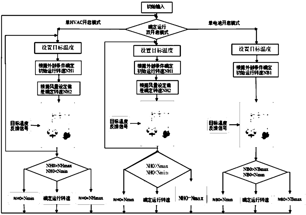
[0004] However, the above-mentioned control method has the following defects: a) In the single HVAC cooling state, the corresponding speed of the compressor is determined by the set speed of the controller. The variable speed will cause the state of high energy under certain operating conditions, and the state of insufficient energy under certain operating conditions; b) In the state of single-battery cooling, the temperature of the battery core is collected through the bus to determine the corresponding state of the compressor. Speed, if the same predetermined speed is used under different environmental conditions, the temperature of the battery core is easily affected by the operating conditions, so there will be energy interference under certain operating conditions, and in some operating conditions c) In the state of HVAC and battery cooling, the superposition of the two methods will cause shocks to the operation of the compressor, and it will not be possible to further implement the correction compensation mode, which will cause discomfort to passengers

Method used


Image

  • New energy automobile refrigeration control method
  • New energy automobile refrigeration control method

Examples


Embodiment Construction

[0020] The technical solutions in the embodiments of the present invention will be clearly and completely described below in conjunction with the drawings in the embodiments of the present invention. Obviously, the described embodiments are only a part of the embodiments of the present invention, rather than all the embodiments. Based on the embodiments of the present invention, all other embodiments obtained by those skilled in the art without creative work shall fall within the protection scope of the present invention.

[0021] The terms "first", "second", "third", etc. (if any) in the description and claims of the present invention and the above-mentioned drawings are used to distinguish similar objects, and not necessarily used to describe a specific order Or precedence. It should be understood that the objects described in this way can be interchanged under appropriate circumstances. In addition, the terms "include" and "have" and any variations of them are intended to co...


PUM


Abstract

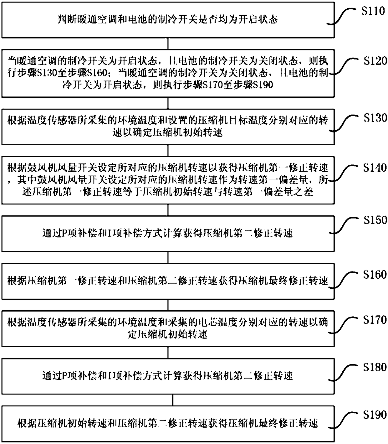
The invention discloses a new energy automobile refrigeration control method. The new energy automobile refrigeration control method comprises the following steps that (a) whether refrigeration switches of a heat ventilation air conditioner and a battery are in an on state or not is judged; (b) when the refrigeration switch of the heat ventilation air conditioner is in the on state, the step (c) to the step (f) are executed and when the refrigeration switch of the heat ventilation air conditioner is in an off state, the step (g) to the step (i) are executed; (c) the compressor initial rotatingspeed is determined according to the rotating speeds corresponding to environmental temperature and set compressor target temperature; (d) the corresponding compressor rotating speed is set accordingto an air blower air volume switch to obtain a first corrected rotating speed of a compressor; (e) a second corrected rotating speed of the compressor is obtained through P-item compensation and I-item compensation ways; (f) a final corrected rotating speed of the compressor is obtained according to the first corrected rotating speed of the compressor and the second corrected rotating speed of the compressor; (g) the compressor initial rotating speed is determined according to the rotating speeds corresponding to the environmental temperature and collected cell temperature; (h) the second corrected rotating speed of the compressor is obtained through P-item compensation and I-item compensation ways; and (i) the final corrected rotating speed of the compressor is obtained according to thecompressor initial rotating speed and the second corrected rotating speed of the compressor.

Description

Technical field [0001] The invention relates to the technical field of refrigeration for new energy vehicles, and in particular to a refrigeration control method for new energy vehicles. Background technique [0002] In the existing single air conditioner control field of new energy vehicles, the compressor speed is mainly determined according to the setting of the controller. The actual speed information of the compressor is sent to the compressor assembly via the CAN bus. The compressor assembly receives the actual speed information through the bus and controls the compressor speed according to the actual speed information. Under normal circumstances, under different ambient temperature, blower air volume, internal and external circulation design, the same speed variable will be used, so there are some operating conditions that are energy interference state, or some operating conditions are energy insufficient state. In addition, the single-cell cooling method also has the abo...

Claims


Application Information

Patent Timeline
Patent Type & Authority Applications(China)
IPC IPC(8): B60H1/00
CPCB60H1/00021B60H2001/0015
Inventor 庄玲华覃峰
Owner SONGZ AUTOMOBILE AIR CONDITIONING
Why Eureka
Try Eureka