Unmanned boat automatic survey system and unmanned boat automatic survey method

A technology for automatic observation and unmanned boats, which is applied in radio wave measurement systems, satellite radio beacon positioning systems, traffic control systems, etc., and can solve problems such as the inability to automatically generate observation routes

Inactive Publication Date: 2010-06-23
CODEN
View PDF1 Cites 12 Cited by
  • Summary
  • Abstract
  • Description
  • Claims
  • Application Information

AI Technical Summary

Problems solved by technology

However, it is not yet possible to automatically generate an observation route and follow the observation route to observe the situation in the water or at the bottom

Method used


Image

  • Unmanned boat automatic survey system and unmanned boat automatic survey method
  • Unmanned boat automatic survey system and unmanned boat automatic survey method
  • Unmanned boat automatic survey system and unmanned boat automatic survey method

Examples


Embodiment 1

[0033] The unmanned boat automatic observation system and the unmanned boat automatic observation method described in Embodiment 1 generate a plurality of observation routes at certain intervals based on the input reference observation line. It is possible to automatically perform underwater and underwater observation by navigating through the plurality of observation routes. The interval of the observation route can be freely set, so for example, in the case of drawing detailed underwater drawings, by setting the interval of the observation route to be narrow, the unmanned boat can travel back and forth at a narrow interval, thereby enabling detailed Earth observation of the bottom of the water.

[0034] First, the configuration of the unmanned boat automatic observation system in Embodiment 1 will be described.

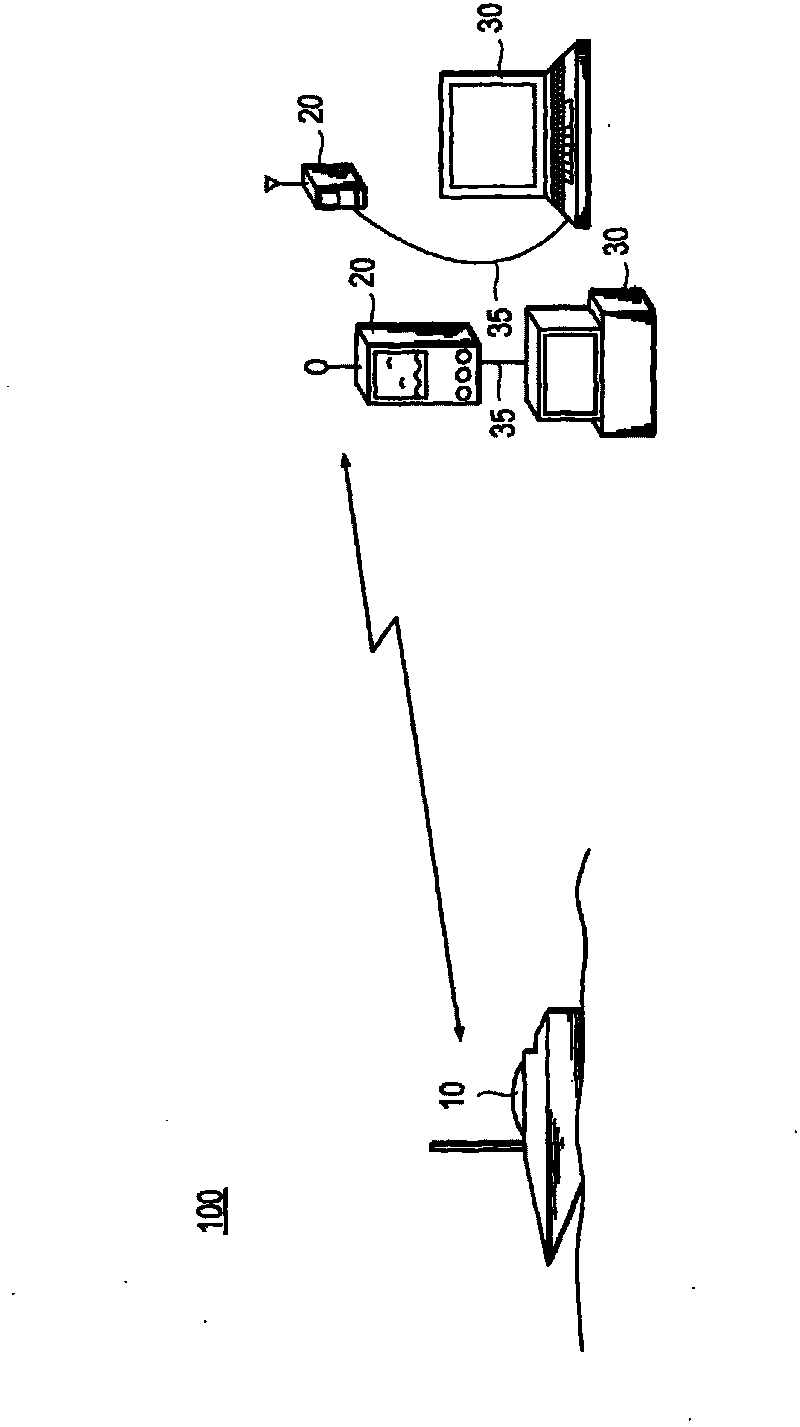
[0035] figure 1 It is a structural diagram of the unmanned boat automatic observation system related to the present invention.

[0036] As shown in the figure, t...

Embodiment 2

[0098] In the unmanned boat automatic observation system and the unmanned boat automatic observation method described in Embodiment 2, in the vertical direction of the measurement line forming the input reference observation line, a straight line extending at a certain interval is generated, thereby generating a plurality of observation routes , by automatically navigating the unmanned boat 10 on the plurality of observation routes, underwater and underwater observations are automatically performed. The interval of the observation route can be freely set, so for example, when a detailed underwater map is desired, by setting the interval of the observation route to be narrow, the unmanned boat 10 can travel back and forth at a narrow interval, and can observe Detailed underwater conditions.

Embodiment 11

[0099] The eleventh embodiment differs from the second embodiment only in that the observation route generation unit 26 included in the wireless controller system 20 is used to create the observation route. Therefore, the configuration of other parts except the observation route generation unit 26 is completely the same as that of the unmanned boat automatic observation system described in Embodiment 1, and thus the description of these configurations and operations will be omitted.

[0100] Figure 11 It is a figure which shows an example of the reference observation line created by the reference observation line creation part 25, Figure 12 is a diagram showing an example of the survey route generated by the survey route generator 26 .

[0101] Figure 5 The reference observation line creation unit 25 included in the wireless controller system 20, such as Figure 11 As shown, a measurement line or arc is created with the two coordinates input through the operation switch ...


PUM


Abstract

The present invention is about an unmanned boat automatic survey device and an unmanned boat automatic surveying method that automatically generate survey routes and automatically survey underwater and water bottom conditions under the survey routes. Under the present invention, a reference survey line is entered for generating a survey route (S1), and a plurality of survey routes are generated by translating the reference survey line at a fixed distance (S2). It then determines the distances of the generated survey routes and instructs a traversing order of the determined survey routes (S3), and causes the unmanned boat to navigate automatically according to the instructed traversing order. It surveys at least underwater or water bottom condition during the navigation (S5), and display and store the surveyed underwater or water bottom condition (S6).

Description

technical field [0001] The invention relates to an unmanned boat automatic observation system and an unmanned boat automatic observation method, in particular to an unmanned boat automatic observation system and an unmanned boat automatic observation method that can automatically observe water or underwater conditions by enabling the unmanned boat to navigate. Background technique [0002] In the observation of water or underwater conditions in seas, lakes, ponds, rivers, etc., unmanned boats that can be remotely controlled are used. The unmanned boat is equipped with sonar, which can emit ultrasonic waves to the bottom of the water, and receive ultrasonic waves reflected from the bottom of the water, so as to observe the situation in the water or the bottom of the water. [0003] For example, as described in Japanese Patent No. 2005-343391, the operator controls the unmanned boat from a remote place to observe the bottom of the desired place. This makes it possible to easi...

Claims


Application Information

Patent Timeline
Patent Type & Authority Applications(China)
IPC IPC(8): G01S15/88G01S15/96G01C21/00B63H25/04G01S19/14G05D1/00
CPCG05D1/0206G08G3/00G05D1/00G01S5/14B63C11/48
Inventor 幸田义治幸田耕二郎
Owner CODEN
Why Eureka
Try Eureka